Now that the build process is complete and the charger is fully functional, let's move on to the Arduino software part. However, before we jump to that, here are the quick specs.
Dual NiMH Battery Smart Charger:
- Charges 2500 mAh NiMH battery cells in up to 3 1/2 hours.
- Handles two battery cells simultaneously and independently.
- Performs prior cell discharge to avoid the memory formation.
- Smart decisions based on cell voltage, temperature and charge/discharge current.
- Charging stops when either of -dV or dT condition happens first.
- LED signaling of the battery state.
Do note that this is a prototype, the first made yet, and that specs are subject to changes - in a good way.
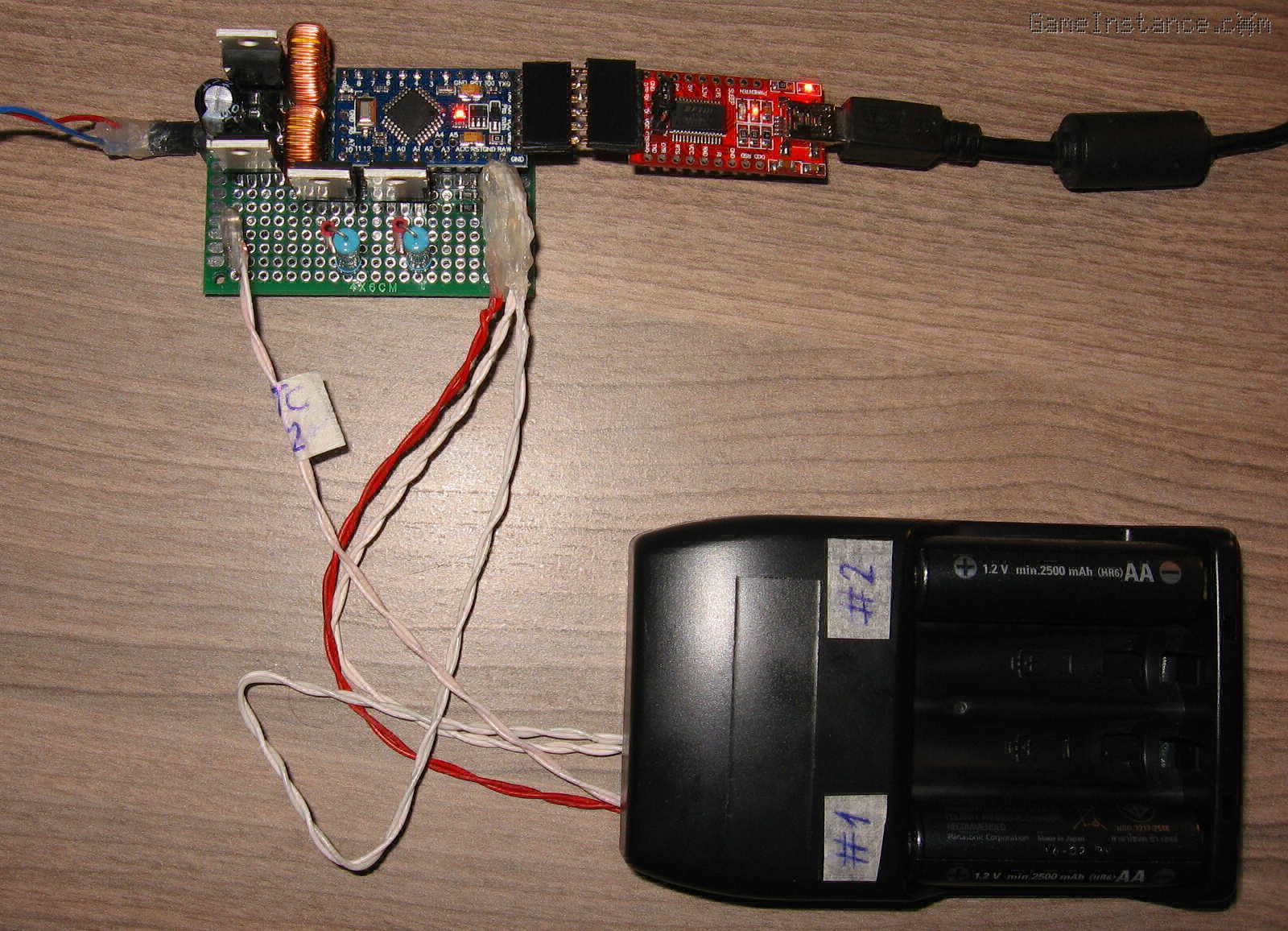
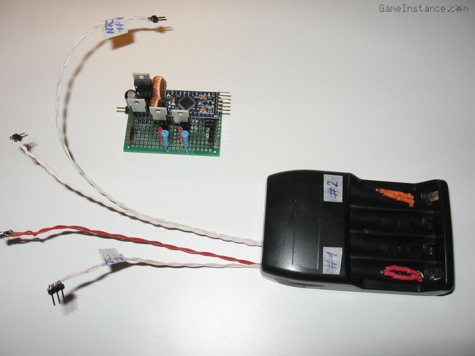 NiMH Smart Dual Battery Charger - the device and the battery mounts.
Overview
The device discharges partially consumed batteries and charges them back. Some batteries cannot tolerate the high 800 mA current charging, so they are charged at 240 mA for many hours. At the end of the charging process, the device stops and signals you to remove the battery.
The charger will refuse alkaline cells based on their open-circuit voltage. If you feed it a sufficiently discharged alkaline battery it will attempt a recharge. Although non-rechargeable alkaline batteries can be recharged for a very limited number of times - you didn't hear that from me - they cannot be recharged at constant current. The battery case wasn't designed to contain pressure build-up caused by recharging. They could rupture, sometimes violently.
Seriously, DO NOT put Alkaline batteries in NiMH chargers!
The charger cannot read the label - not yet - but you can.
Hardware limits
Both buck-converter sections of the smart charger seem to perform with little switching or rectification loss. I tested both channels for 24 hours at 1 A output current. As expected, the power resistors were reaching skin-burning temperatures. The first 30 minutes they produced some stinky fumes - probably burned out whatever coating they had. That is why I chose to dial-down the maximum output current. Not only this will extend the service life of the resistors but it makes the device a tad safer to use. 800 mA is still suitable for fast charging, meaning around C/3 for most AA 1.2V NiMH cells available these days.
The N-Channel MOSFET of each discharger engages and disengages the corresponding power resistor with negligible delay. Once on, the power resistor sees between 550 mA and 810 mA, well within reasonable limits. However, the issue here is somewhat negligible: the discharge current drops proportionally with the cell voltage. That's because the consumer has a constant resistance.
The sketch
bends the Arduino set of rules. It uses oversample and decimation to improve the ADC resolution up to 16 bit and fiddles with the PWM signal generation mechanism to get 11 bit resolution and a frequency of 8 kHz. That means better accuracy in generating the constant current and lower ripple at the output. Rules are in order for a reason, however, as not all the PWM capable pins can attain those specs without affecting time tracking functions of the Atmega. To avoid that, the sketch will tamper with timer1, controlling PWM on pins 9 and 10. This means the device has to use only those two pins.
The code relies on two instances of the BatteryCharger class, one for each charger/discharger section. Each object enters a waiting state upon startup until a battery is put into its designated slot. It measures the open-circuit voltage, the voltage under a 1.8 Ohm load and its temperature. It decides whether it needs discharging and proceeds to it. After the eventual discharge, it then moves on to recharging it.
With age, use habits and number of cycles, the internal resistance of a battery inevitably increases. That resistance behaves like a resistor in series with the ideal - open circuit - voltage of the cell. Charging such batteries under high current will cause the cell to heat-up, exacerbating its declining state. As such, based on internal resistance determination, these cells will be charged slowly, at a low current. The charger will stop after 15 hours or when the battery temperature goes above 35 °C.
Deeply discharged cells will also be recharged at a low current. They too present an initial high internal resistance, so they fit in the above-mentioned section.
For properly used, good cells - with low internal resistance - the high current charging procedure is applied. Primary parameters such as voltage, current inflow and temperature are constantly measured. The charging stops if there's a 10 mV drop in voltage or when the temperature ramps-up too quickly. As a safety measure, the charger stops when cell voltage surpasses a certain maximum value or after 5 hours. Several other cell protective measures are employed in case of a device failure.
/*
 * NiMH dual cell smart charger
 * using the Arduino328p
 *
 * GameInstance.com
 * 2017
 */
#include "NTCThermistor.h"

static const byte V_BAT0 = A1;
static const byte V_BAT1 = A0;
static const byte I_BAT0 = A6;
static const byte I_BAT1 = A7;
static const byte NTC0 = A3;
static const byte NTC1 = A2;

static const byte CH_PWM0 = 9;
static const byte CH_PWM1 = 10;
static const byte DSCH_0 = 12;
static const byte DSCH_1 = 11;
static const byte LED_0 = 13;
static const byte LED_1 = 100; // NOT USED

static const float I_HIGH_CURRENT_CHARGING = 0.8; // amps
static const float I_LOW_CURRENT_CHARGING = 0.24; // amps
static const float V_BAT_MIN = 0.5; // volts
static const float V_BAT_CHARGE = 1.0; // volts
static const float V_BAT_MAX_NIMH = 1.475; // volts
static const float V_BAT_MAX = 1.8; // volts
static const float VOUT_MAX = 4.0; // volts
static const float VCC = 5.02; // volts
static const float SHUNT_RESISTOR = 1.8; // ohms

static const byte LED_NONE = 0;
static const byte LED_WAITING = 1;
static const byte LED_DISCHARGING = 2;
static const byte LED_CHARGING = 3;
static const byte LED_READY = 4;
static const byte LED_ERROR = 5;


void ConfigPWM() {
  // fast PWM non-inverting and no prescaling
  // using 2047 as the max counter value
  // on pins 9 and 10
  DDRB |= _BV(PB1) | _BV(PB2);
  TCCR1A = _BV(COM1A1) | _BV(COM1B1) | _BV(WGM11);
  TCCR1B = _BV(WGM13) | _BV(WGM12) | _BV(CS10);
  ICR1 = 2047;
}

void SetPWM(unsigned char pin, unsigned int value) {
  // sets the PWM level
  switch (pin) {
    //
    case 9:
      //
      OCR1A = value;
      break;

    case 10:
      //
      OCR1B = value;
      break;
  }
}


class BatteryCharger {

  public:

    /// default constructor
    BatteryCharger() :
      state(0) {
      //
      ntc.Config(100000, 25, 3950, 100250, 65536);
    }
    /// destructor
    virtual ~BatteryCharger() {
      //
    }

    /// configures the object
    void Config(
      unsigned char vbat_pin,
      unsigned char ibat_pin,
      unsigned char tbat_pin,
      unsigned char pwm_pin,
      unsigned char dschrg_pin,
      unsigned char led_pin,
      unsigned char id) {
      //
      pin_vbat = vbat_pin;
      pin_ibat = ibat_pin;
      pin_tbat = tbat_pin;
      pin_pwm = pwm_pin;
      pin_dschrg = dschrg_pin;
      pin_led = led_pin;
      iid = id;
    }
    /// executes the automate
    void Execute() {
      //
      ExecuteLED();
      .. check the GitHub repo for the complete, up-to-date code
    }

  private:

    /// reads and accumulates multiple samples and decimates the result
    static unsigned long ReadMultiDecimated(byte pin, byte bits = 16) {
      //
      unsigned long total = 0;
      bits -= 10;
      int N = B00000001 << (2 * bits);
      for (int i = 0; i < N; i++) {
        //
        total += analogRead(pin);
      }
      return total >> bits;
    }
    /// gets the voltage from the given ADC value
    static double GetVoltage(unsigned long value, unsigned long resolution = 1024, float vcc = VCC) {
      //
      return (double) value / (resolution - 1) * vcc;
    }
    /// sets the PWM level for the charger's buck converter
    void SetCharger(unsigned int level) {
      //
      level_pwm = level;
      SetPWM(pin_pwm, level_pwm);
    }
    /// turns on and off the discharger
    void SetDischarger(bool on) {
      //
      digitalWrite(pin_dschrg, on ? HIGH : LOW);
    }
    /// sets the LED state
    void SetLED(unsigned char state) {
      //
      stateLED = state;
      LEDon = false;
      digitalWrite(pin_led, LOW);
    }
    /// executes the LED sequence
    void ExecuteLED() {
      //
      if (stateLED == LED_NONE) {
        // do nothing
        return;
      }
      // do something
      if (stateLED == LED_READY) {
        //
        if (!LEDon) {
          //
          LEDon = true;
          digitalWrite(pin_led, HIGH);
        }
        return;
      }
      if (millis() > LED_ts) {
        //
        if (LEDon) {
          //
          LEDon = false;
          digitalWrite(pin_led, LOW);
        } else {
          //
          LEDon = true;
          digitalWrite(pin_led, HIGH);
        }
        if (stateLED == LED_WAITING) {
          //
          LED_ts = millis() + 500;
        } else if (stateLED == LED_DISCHARGING) {
          //
          LED_ts = millis() + LEDon ? 250 : 750;
        } else if (stateLED == LED_CHARGING) {
          //
          LED_ts = millis() + LEDon ? 750 : 250;
        } else if (stateLED == LED_ERROR) {
          //
          LED_ts = millis() + LEDon ? 250 : 250;
        }
      }
    }

    /// state
    unsigned char state = 0;
    /// instance id
    unsigned char iid = 0;
    /// the ADC read value for Vbat
    unsigned int value_vbat = 0, value_ibat = 0;
    /// measured voltages
    double voltage_vbat = 0.0f, voltage_ibat = 0.0f, voltage_vbat_noload = 0.0f;
    /// end-charging primary variables
    double voltage_max = 0.0f, temperature_last = 0.0f;
    /// end-charging secondary variables
    double temperature_slope = 0.0f, voltage_drop = 0.0f;
    /// measured temperature
    double temperature = 0.0f;
    /// determined shunt current
    double current = 0.0f;
    /// determined powers
    double capacity_in = 0.0f, capacity_out = 0.0f;
    /// input Vbat, Ibat, Tbat pins
    unsigned char pin_vbat, pin_ibat, pin_tbat, pin_led;
    /// control charge_pwm and discharge pins
    unsigned char pin_pwm, pin_dschrg;
    /// LED sequence state
    unsigned char stateLED = 0;
    /// LED state
    bool LEDon = false;
    /// timestamps
    unsigned long now_ts = 0, end_ts = 0, ts = 0, LED_ts = 0;
    /// pwm level
    unsigned int level_pwm = 0;
    /// pwm level increment
    signed char level_pwm_increment = 0;
    /// thermistor probe
    NTCThermistor ntc;
};


BatteryCharger charger_0, charger_1;

void setup() {
  //

  pinMode(V_BAT0, INPUT);
  pinMode(V_BAT1, INPUT);
  pinMode(NTC0, INPUT);
  pinMode(NTC1, INPUT);
  pinMode(A4, OUTPUT);
  pinMode(A5, OUTPUT);
  pinMode(I_BAT0, INPUT);
  pinMode(I_BAT1, INPUT);
  for (int i = 2; i <= 13; i ++) {
    //
      pinMode(i, OUTPUT);
      digitalWrite(i, LOW);
  }
  digitalWrite(A4, LOW);
  digitalWrite(A5, LOW);

  charger_0.Config(V_BAT0, I_BAT0, NTC0, CH_PWM0, DSCH_0, LED_0, 1);
  charger_1.Config(V_BAT1, I_BAT1, NTC1, CH_PWM1, DSCH_1, LED_1, 2);

  // sets the PWM resolution to 11 bits at 8kHz
  ConfigPWM();
  SetPWM(CH_PWM0, 0);
  SetPWM(CH_PWM1, 0);

  Serial.begin(9600);
}

void loop() {
  //

  charger_0.Execute();
  charger_1.Execute();
}
Please check-out the GitHub repo for the complete, up-to-date version of the code.
Al fine
Some may say that all this effort was overkill and that NiMH batteries are inexpensive commodity products nowadays. That may be true but when it comes to properly built cells, it is a darn shame and a waste of resources to have them toast in timer-based chargers.
Besides, look at it!
Doesn't it look nice? Isn't this the reason you're here?
Full of doubts, are you? Yes-yes-yes! [master Yoda impression] Well, here's the voltage evolution over time for a 2500 mAh cell charged at 800 mA constant current.
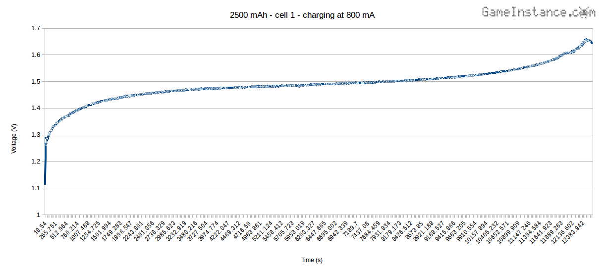
The chart shows that the charger is performing its task and stopping at the right moment, in this case upon -dV = 10 mV detection. The chart also indicates that the battery absorbed approximately 2750 mAh, around 110% of its capacity, meaning that it just slightly overcharged. Still, this is far better than what timer-based chargers do, so this device is a keeper!
Bottom line is that a smart charger, such as this one, will take better care of rechargeable cells and that means they will last longer.
Update: Check-out the next article on how to Reduce NiMH battery overcharging by making better use of temperature increase rate information.