This is a follow-up of my previous article on how to DIY an Arduino Smart NiMH battery charger. It includes the complete circuit diagram along with explanations for the choices made, some tips and a guide for the build procedure. I've also written a simple Arduino test sketch that will help verify the functionality of your build, should you decide to make a similar tool.
The circuit
relies on a non-synchronous buck converter controlled by the Atmega328. Here's the new diagram containing all the components:
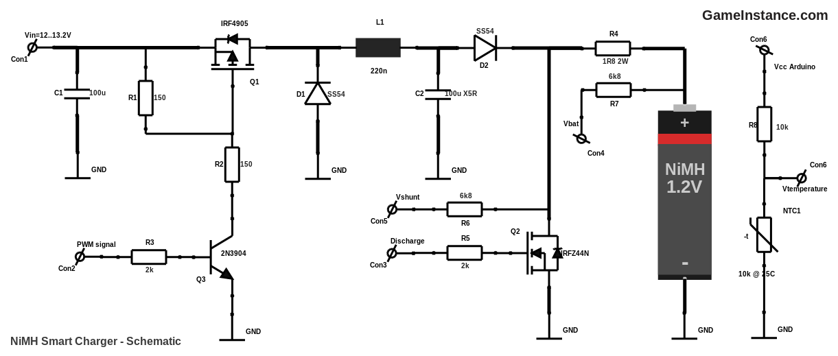
You may have noticed the presence of D2, a Schottky diode, between the buck's output and the current sensing shunt resistor. It was placed there to prevent an accidental short-circuit of the NiMH cell in case either the power source or the buck-converter fails. Take the X5R ceramic C2 capacitor for example, should it go bad, it will short-circuit. This will silently and completely discharge the cell, rendering it useless. It is worth reiterating that the primary purpose of the circuit is to protect the battery at all cost. Charging it, should it be possible, comes second.
The Arduino Pro Mini, harboring the MCU, is missing from the circuit diagram for readability and simplicity reasons. However, here's how you can connect it: PWM signal goes to a PWM capable output pin on the Arduino board, the Discharge can be hooked to any pin that can be configured as output while Vbat, Vshunt and Vtemperature need to be connected to any of the analog input pins. Also missing from the schematics above is an external regulator, an AMS117, that generates the VCC for Arduino from the input voltage VIN.
Because the Arduino Pro Mini board breaks-out more than twice the number of pins required for this project, I'll double the stakes. That means the circuit will handle two batteries at the same time. Also, it will require more parts and more work. Quite a gamble!
With no further ado, here's what you need:
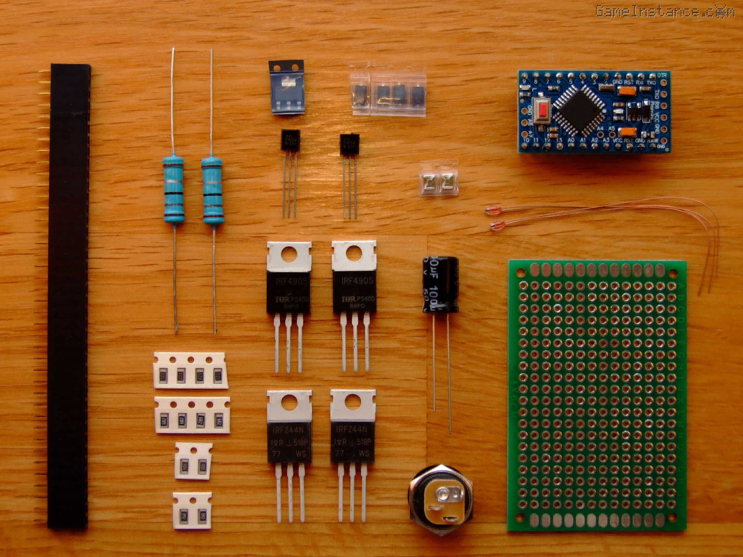 Dual NiMH Battery Smart Charger - List of components
Bill Of Materials (for dual charger circuit):
MCU1 - 1x Arduino Pro Mini featuring the Atmega328
Q1 - 2x IRF4905 P-Channel MOSFET RDSon=20.0mOhm
Q2 - 2x IRFZ44N N-Channel MOSFET RDSon=17.5mOhm
Q3 - 2x 1N3904 Small Signal NPN transistor
D1,2 - 4x SS54 Schottky diodes, VF=0.48V @ 1A, 25 degC
R1,2 - 4x 220 Ohm 0.25W resistors
R4 - 2x 1.8 Ohm 2W power resistors
R3,5 - 4x 2 kOhm 0.25W resistors
R6,7 - 4x 6.8 kOhm 0.25W resistors
R8 - 2x 10 kOhm 0.25W resistors
NTC1 - 2x 10 kOhm at 25deg C, NTC thermistor
C1 - 1x 100 uF 16V electrolytic capacitor
C2 - 2x 100 uF 16V X5R ceramic capacitor
L1 - 2x 220 nF inductor
Miscelaneous:
External voltage regulator AMS1117, 5V
Female header connectors
PCB prototyping board 4cm x 6cm
Multi-color wires
Build guidelines
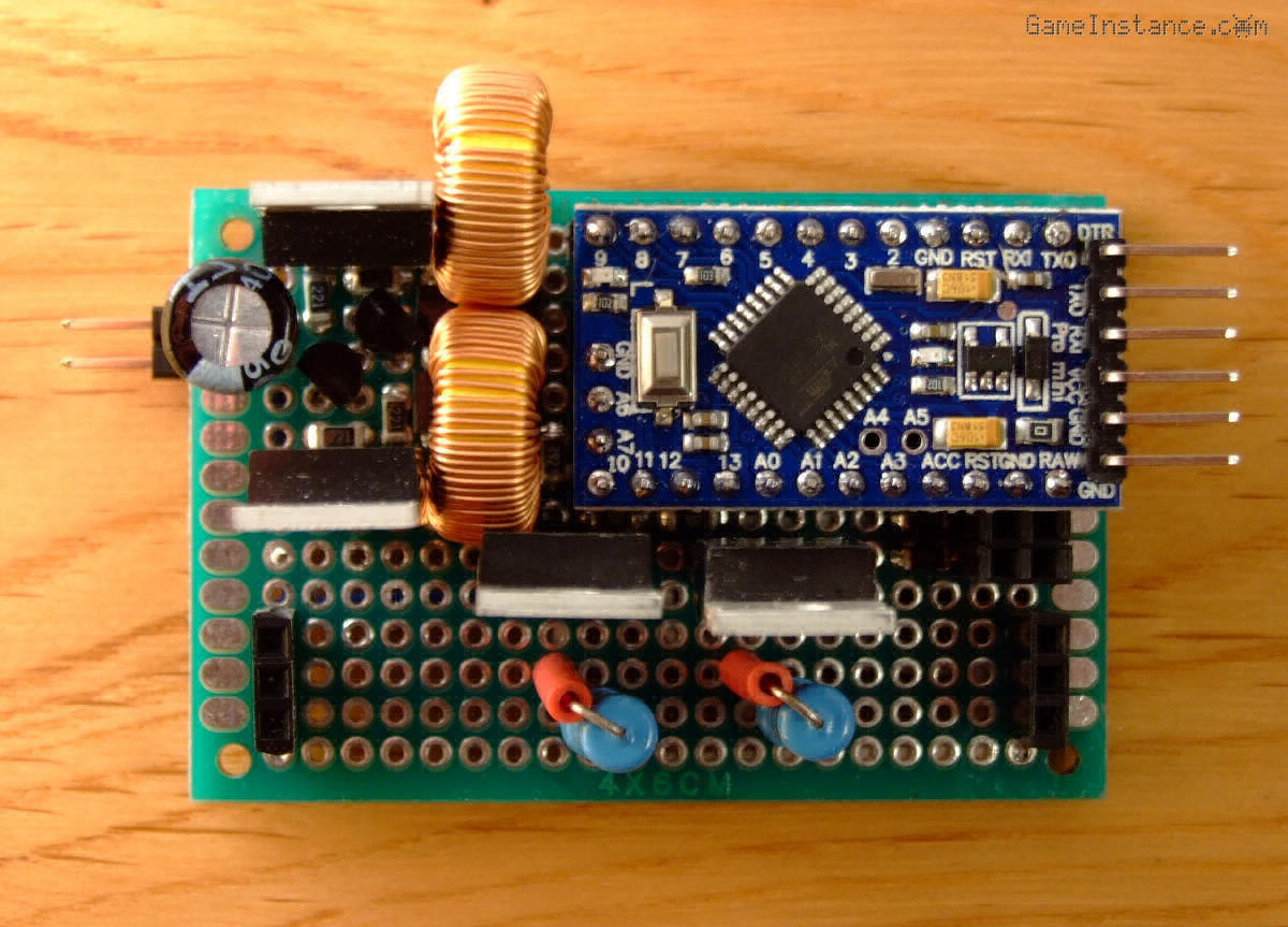
The component face - always start by soldering the smallest components first. That means the resistors, X5R capacitors, diodes, the signal transistors and the header connectors. Solder X5R capacitors as fast as you can. Exposing them to heat for too long will cause cracks leading to their failure. Aiming at a smaller footprint on the already crowded PCB, I've soldered the power resistors vertically. They've been positioned in a less populated area to allow a better cooling. Inductors are by far the biggest components, measuring 13x5 mm, so they were placed last.
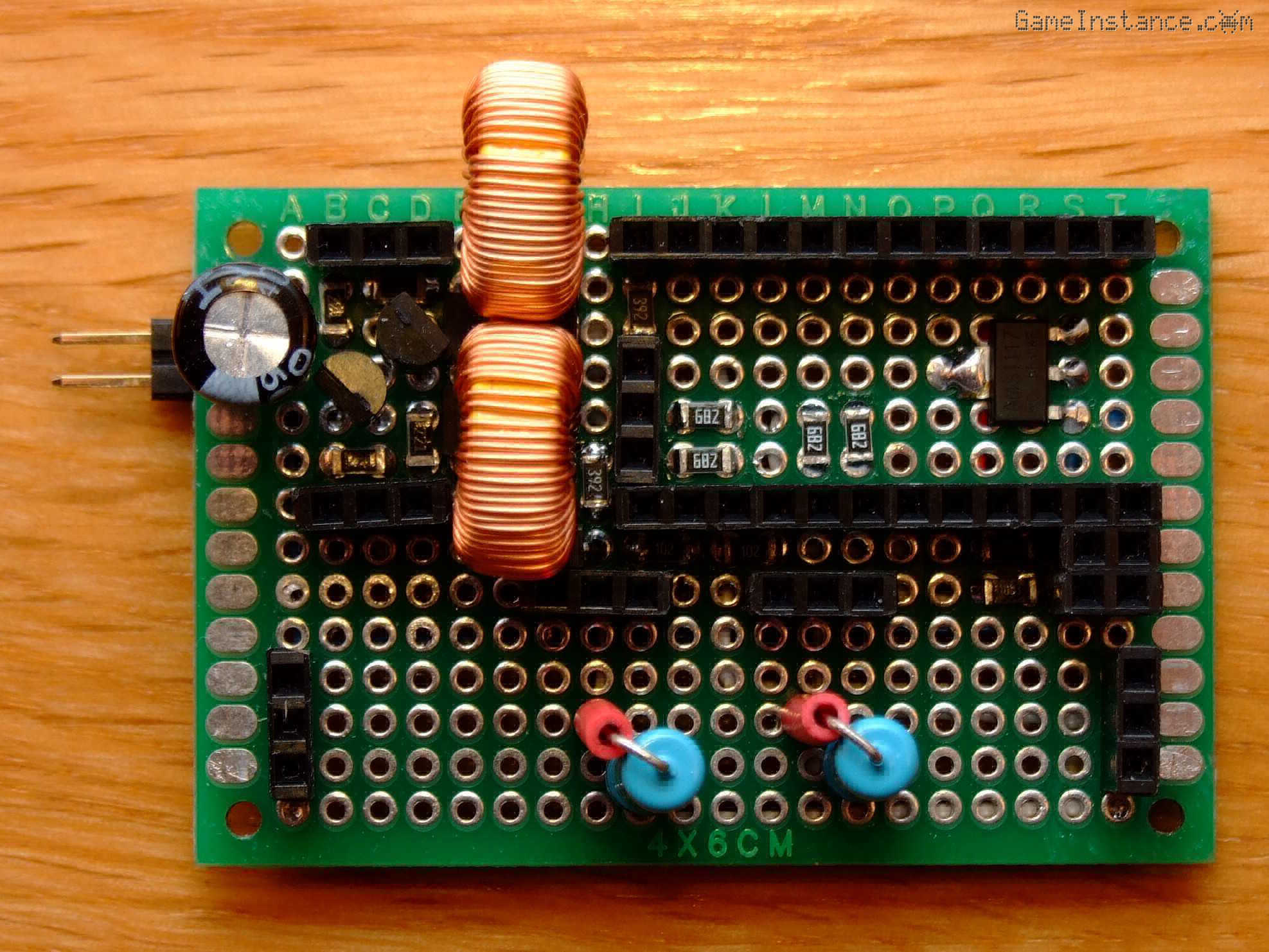 NiMH Dual Cell Smart Charger - Component face
Once more, I advise in favor of using header connectors. They add modularity and unmatched flexibility to the circuit. I've used them for bridging the Arduino Pro Mini board and the power transistors to the prototyping PCB. In case one of them breaks, the replacement would be a breeze. Besides, if an Arduino Pro Mini board or a MOSFET is urgently needed in another project, I can re-deploy them in an instant. Headers can be used for small signal connections but also for power connections. Yeah, they can withstand 1 amp. However, I wouldn't use them for more than that.
The wiring face - start by connecting the points from the middle of the board and those with the smallest distance in-between. The longer lines, generally high power ones, can be router over them. Remember not to position wires over places you'll solder junctions later on. That means having a placement and wiring plan made in advance. It's easier than it sounds.
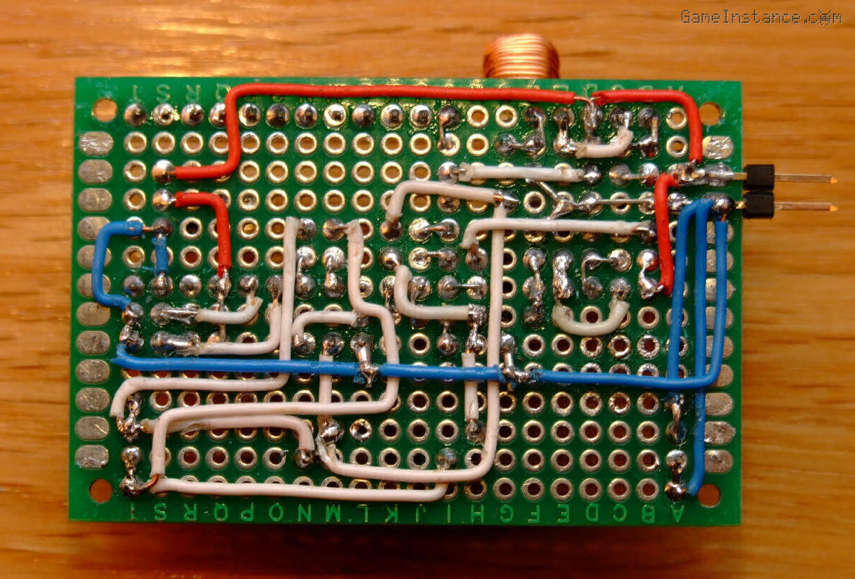 NiMH Dual Cell Smart Charger - Wiring face
Now, the wiring isn't great but it doesn't look half as bad as I was expecting. It turned out reasonably nice given the density of SMD and through hole components. It works and that's what's important.
 NiMH Dual Cell Smart Charger - Arduino board and MOSFETs in place
Warning:
The 2W power resistor R2 will heat-up both during charging and discharging of a NiMH cell. Make sure you keep temperature sensitive components away - NTC is one of them. Also, remember that exposing a NiMH cell to high temperatures while charging will inevitably shorten its life.
Battery slots
I've removed the internals from an old charger and I used the case for the AA battery slots. This particular model had slots for AAA type of cells beneath the AA ones, making them suitable for placing the NTC thermistors. They make good thermal contact with the battery cells and are well insulated from ambient air that may influence the temperature readings.
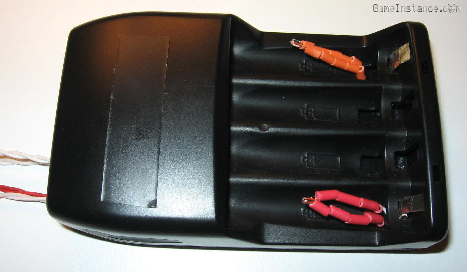 Using the AA cell slots from an old NiMH charger. NTC thermistors now occupying the AAA slots.
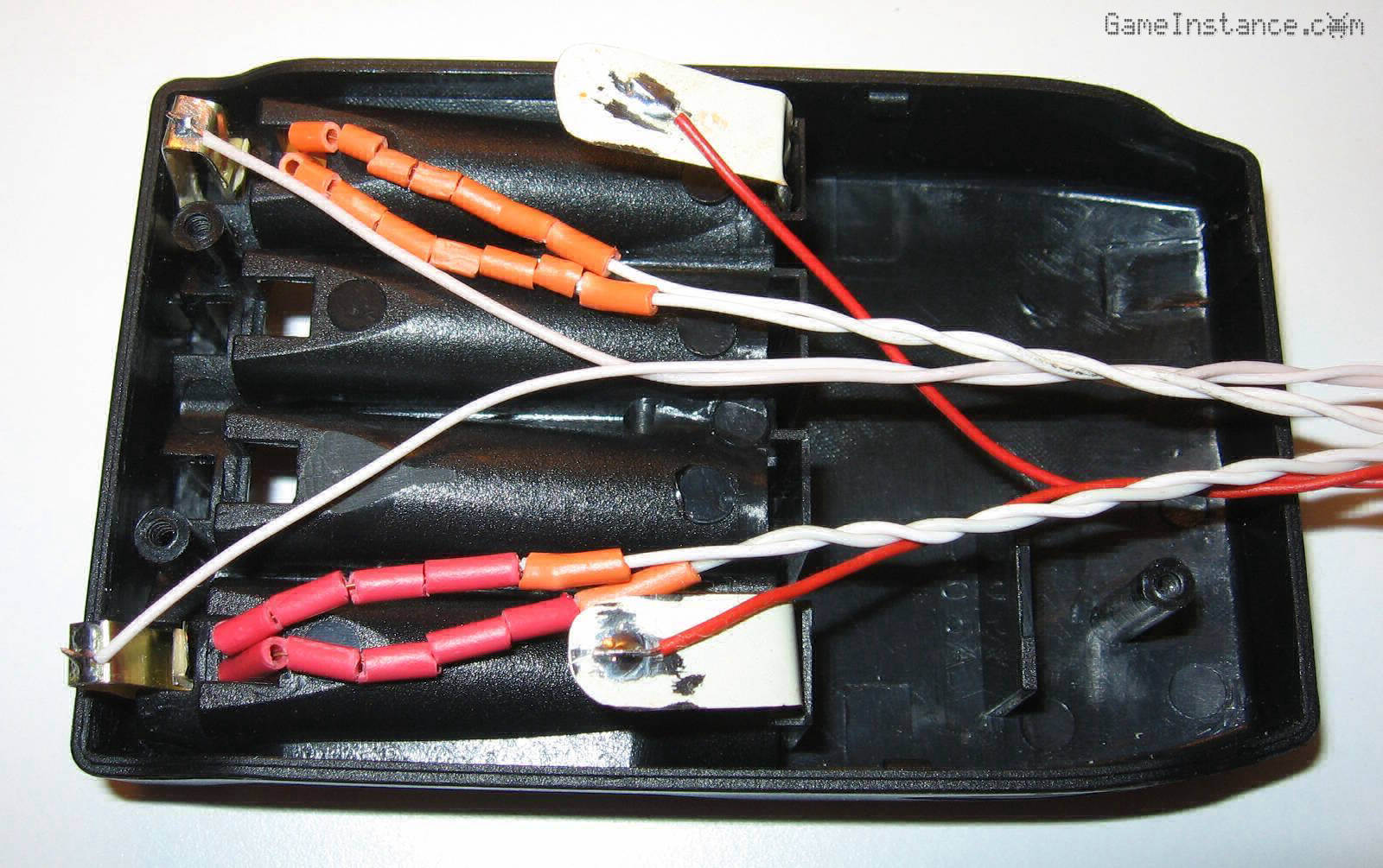 Hand-made, tin sheet contacts for the AA cells and NTC thermistor on the back of an old NiMH charger.
Function test
When you feel confident about the wiring of your rig, you can move on to testing its function. As a reminder, it is supposed to provide constant current onto a load that, for this project, is a NiMH battery. However, you'll want to see it performing like a buck-converter. Thus, the first test should be made with a different consumer. Use any low power light bulb or DC motor rated for at least 12V. I've used a 12V DC motor.
Compile and flash the following test sketch. Once you've connected the 12V power supply at the VIN, you should be able to notice a sequential power increase within the consumer. If that's the case, congrats, you're done with the agonizing part.
static const byte CH_PWM0 = 9;
static const byte CH_PWM1 = 10;

static const byte V_BAT0 = A1;
static const byte V_BAT1 = A0;
static const byte V_SHUNT0 = A6;
static const byte V_SHUNT1 = A7;

static const float VCC = 5.00; // volts
static const float R_SHUNT = 1.8; // ohms

void setup() {
  // put your setup code here, to run once:
  Serial.begin(9600);
}

void loop() {
  // put your main code here, to run repeatedly:
  for (int level = 0; level < 255; level += 16) {
    //
    analogWrite(CH_PWM0, level);
    analogWrite(CH_PWM1, level);
    Serial.print(millis());
    Serial.print(" PWM = ");
    Serial.print(level);
    Serial.print(": Vout0=");
    Serial.print((double) analogRead(V_BAT0) / 1023 * VCC, 4);
    Serial.print("V, Iout0=");
    Serial.print((double) (analogRead(V_SHUNT0) - analogRead(V_BAT0)) / 1023 * VCC / R_SHUNT, 4);
    Serial.print("A, Vout1=");
    Serial.print((double) analogRead(V_BAT1) / 1023 * VCC, 4);
    Serial.print("V, Iout1=");
    Serial.print((double) (analogRead(V_SHUNT1) - analogRead(V_BAT1)) / 1023 * VCC / R_SHUNT, 4);
    Serial.println("A");
    delay(2000);
  }
}
This concludes the construction phase. Stop-by again for the complete software part of this project.
Update: Check-out Dual NiMH Battery Smart Charger - part 3, the Arduino sketch.