This article proposes a simple Arduino based tool that monitors the voltage drop and current through a speaker for the purpose of measuring its impedance. The raw values are passed on demand to a dual purpose python application via serial connection. The results can later be visualized using something like LibreOffice Calc.
Overview
Imagine a loop that begins and ends with the same python app, one that generates tones on your PC's sound adapter and parses incoming serial data. The tones are amplified and reach the speaker in question. Speaker's electrical parameters are watched by the Arduino device. The later sends back data to the python app, closing the measurement loop.
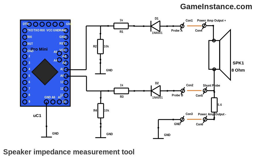 Speaker impedance measurement tool. Arduino Pro Mini fed with half wave rectified signals.
The device
Is composed of an Atmega328p Pro Mini board having two of the analog inputs fed with half-wave rectified signals. The rectification is made by D1 and D2 diodes while the R1-R2 and R3-R4 resistors present a reasonably light load for the S/H capacitor. The first signal is measuring the drop on the shunt resistor - indirectly giving the current through the speaker - and the second signal represents the overall voltage drop.
Special attention needs to be given to result interpretation. The read voltages are slightly distorted by the D1, D2 diodes and the R1-R2, R3-R4 voltage dividers. Luckily the distortions are predictable and the real values can be extracted at a later processing step. Diodes exhibit a typical 0.5V-0.6V forward voltage drop at low currents - the ones involved in this measurement are very small, less than 5 mA - and these voltages can safely be considered constant.
The Arduino sketch
Waits for a command over serial connection and triggers the voltage reads. The results are sent back over the same serial connection. The half-wave rectified tones have enough noise to make them suitable for oversampling and so the code uses multiple 10 bit reads to obtain 16 bit precision.
#include <SerialCommand.h>  // https://github.com/gameinstance/lib-arduino

static const byte CURRENT_PROBE = A0;
static const byte SIGNAL_PROBE = A1;
static const float VCC_ARDUINO = 5.05;      // volts
static const int ADC_RESOLUTION = 65536;    // units
static const int ADC_RESOLUTION_BITS = 16;  // units

unsigned long curent_value = 0, signal_value = 0;
double curent_voltage = 0, signal_voltage = 0;

unsigned long ReadMultiDecimated(byte pin, byte bits = ADC_RESOLUTION_BITS) {
  //
  unsigned long total = 0;
  bits -= 10;
  int N = B00000001 << (2 * bits);
  for (int i = 0; i < N; i++) {
    //
    total += analogRead(pin);
  }
  return total >> bits;
}

double GetVoltage(
  unsigned long value,
  unsigned long resolution = ADC_RESOLUTION,
  float vcc = VCC_ARDUINO) {
  //
  return (double) value / (resolution - 1) * vcc;
}

class MySerialCommand : public SerialCommand {

  public:

    /// default constructor
    MySerialCommand() : SerialCommand() {
      //
    };
    /// destructor
    virtual ~MySerialCommand() {
      //
    };


  protected:

    /// runs the command
    bool Run() {
      //
      switch (data[0]) {
        //
        case '?':
          // identify
          Identify();
          return true;
        case 'p':
          // probes the voltages
          Probe();
          return true;
      }
      // unknown command
      Serial.println("Unknown command!");
      return false;
    };
    /// identifies the app
    void Identify() {
      //
      Serial.println("Speaker Impedance Measurement - GameInstance.com");
    };
    /// proves the voltages
    bool Probe() {
      //
      delay(250);
      curent_value = ReadMultiDecimated(CURRENT_PROBE);
      curent_voltage = GetVoltage(curent_value);
      signal_value = ReadMultiDecimated(SIGNAL_PROBE);
      signal_voltage = GetVoltage(signal_value);
      Serial.print(curent_voltage, 10);
      Serial.print(" ");
      Serial.println(signal_voltage, 10);
    };
};

MySerialCommand sc;

void setup() {
  //
  for (int i = 2; i <= 13; i ++) {
    //
      pinMode(i, OUTPUT);
      digitalWrite(i, LOW);
  }
  pinMode(CURRENT_PROBE, INPUT);
  pinMode(SIGNAL_PROBE, INPUT);
  Serial.begin(9600);
}

void loop() {
  //
  if (sc.Read()) {
    //
    sc.Execute();
  }
}
A better ADC resolution can be obtained by reducing the Vcc from 5V to 3.3V, with the inherent clock speed reduction and increased acquisition times. For accurate readings and to protect the MCU's inputs, make sure that the overall voltage drop, on the speaker and shunt that is, does not exceed Vcc. Also, the shunt resistor should have a suitable power rating: a 2W 5R6 resistor would suffice for the example above.
The Python code
Requires pyaudio module to generate a predetermined number of tones from a given spectrum of frequencies and serial to communicate with the Arduino based device. It starts with the lowest frequency in the spectrum and continues to the highest with a logarithmic step. For each tone, the app sends a p command to the device and allows it sufficient time to perform the oversampled measurements and to respond.
#! /usr/bin/python

import numpy
import pyaudio
import math
import serial
from time import sleep

class ToneGenerator(object):

    def __init__(self, samplerate=44100, frames_per_buffer=4410):
        self.p = pyaudio.PyAudio()
        self.samplerate = samplerate
        self.frames_per_buffer = frames_per_buffer
        self.streamOpen = False

    def sinewave(self):
        if self.buffer_offset + self.frames_per_buffer - 1 > self.x_max:
            # We don't need a full buffer or audio so pad the end with 0's
            xs = numpy.arange(self.buffer_offset,
                              self.x_max)
            tmp = self.amplitude * numpy.sin(xs * self.omega)
            out = numpy.append(tmp,
                               numpy.zeros(self.frames_per_buffer - len(tmp)))
        else:
            xs = numpy.arange(self.buffer_offset,
                              self.buffer_offset + self.frames_per_buffer)
            out = self.amplitude * numpy.sin(xs * self.omega)
        self.buffer_offset += self.frames_per_buffer
        return out

    def callback(self, in_data, frame_count, time_info, status):
        if self.buffer_offset < self.x_max:
            data = self.sinewave().astype(numpy.float32)
            return (data.tostring(), pyaudio.paContinue)
        else:
            return (None, pyaudio.paComplete)

    def is_playing(self):
        if self.stream.is_active():
            return True
        else:
            if self.streamOpen:
                self.stream.stop_stream()
                self.stream.close()
                self.streamOpen = False
            return False

    def play(self, frequency, duration, amplitude):
        self.omega = float(frequency) * (math.pi * 2) / self.samplerate
        self.amplitude = amplitude
        self.buffer_offset = 0
        self.streamOpen = True
        self.x_max = math.ceil(self.samplerate * duration) - 1
        self.stream = self.p.open(format=pyaudio.paFloat32,
                                  channels=1,
                                  rate=self.samplerate,
                                  output=True,
                                  frames_per_buffer=self.frames_per_buffer,
                                  stream_callback=self.callback)

def bytes_to_int(bytes):
    result = 0
    for b in bytes:
        result = result * 256 + int(b)
    return result

###############################################################################

generator = ToneGenerator()

amplitude = 0.90            # Amplitude of the waveform

frequency_start = 20        # Frequency to start the sweep from
frequency_end = 200       # Frequency to end the sweep at
num_frequencies = 180       # Number of frequencies in the sweep
step_duration = 3        # Time (seconds) to play at each step

ser = serial.Serial('/dev/ttyUSB0', 9600, timeout=0)
print(ser.name)
sleep(3);

for frequency in numpy.logspace(math.log(frequency_start, 10),
			math.log(frequency_end, 10),
			num_frequencies):

	generator.play(frequency, step_duration, amplitude)
	ser.write(str("p\n").encode())
	line = ser.readline()
	v = line.split()
	if (len(v) == 2):
		print("%0.2f %0.10f %0.10f" % (frequency, float(v[0]), float(v[1])))
	else:
		print("{0:0.2f} 0 0".format(frequency))
#	print(line)
	while generator.is_playing():
		pass	# Do something useful in here (e.g. recording)

ser.close()
The ToneGenerator class comes from Mark Hedley Jones, so many thanks to him for this.
The reason
My loudspeakers have been ready for some weeks and have been firing decibels left, right and especially forward. Something's missing in the bass department though and that's been occupying my mind lately. The enclosure has the correct volume, the vent is properly sized, the walls are braced, lined and there's some damping material in each box. With doubts about my version of Classix II, I have devised this test gadget.
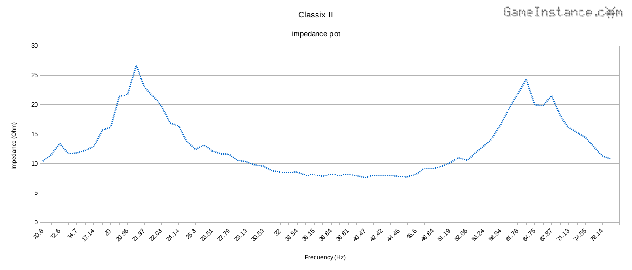 Impedance plot for Classix II speakers with no crossover, zero damping and carpeted inner walls.
The above chart represents the impedance of a Classix II speaker, with the cross-over removed and no polyfil, as it was measured by the device. It indicates that the box is perfectly tuned to 40 Hz - as per design - and exhibits a Ql=9.14 . Recalculating the frequency response with the new data, we get the following:
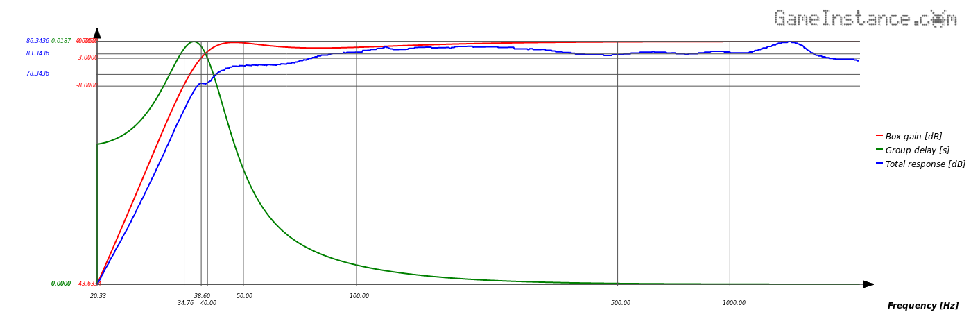 Classix II, the recalculated frequency response using newly determined Ql=9.14 .
The blue line shows the overall frequency response of the loudspeaker. It looks like there is bass all the way down to 38 Hz but not at the same level as low-mids and maybe the highs. There's a 3-4dB gap that is audible, confirming my initial impression.
The conclusion
The Arduino impedance measurement device did its part without a glitch. It is fairly simple to build and easy to use. Virtually any rectification diode would do as long as its forward drop is taken into account when processing result. However, this tool measures only the electrical parameters of a loudspeaker or a speaker. The sound pressure level (SPL) measurement is made using a specialized microphone and does not make the subject of this article.