My previous post summarized a simple automated plant irrigation system capable of watering on its own and off-the-grid a small balcony or apartment garden for several weeks. This article details the electronics involved in the project.
The controller
uses an Atmega 328p backed by a real-time clock for accurate time tracking. The I2C RTC circuit plays a critical role in the system in that it indicates the time with a given precision. Without it, the timing will have to be based on the MCUs internal timer. If, however, something were to go wrong - and it often does - and the controller resets, the timer will start from zero and the entire irrigation cycle will be affected. The plants will end-up being watered more or less often that it should.
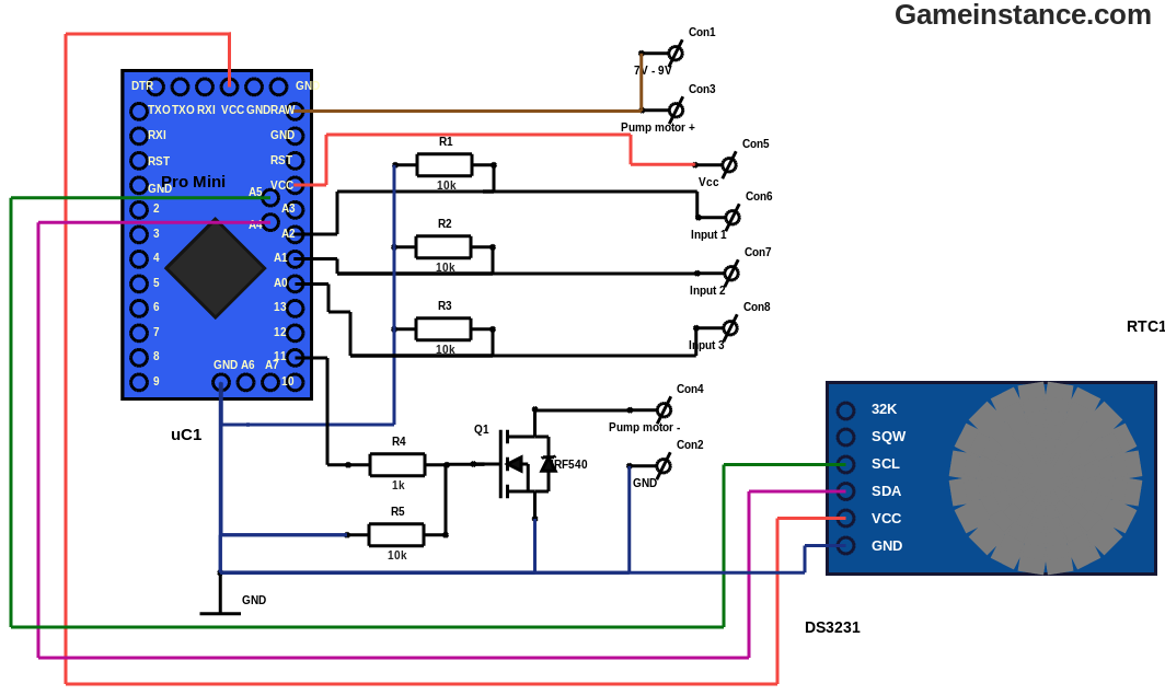 The irrigation system control circuit - featuring Arduino Pro Mini (Atmega 328p) and DS3231 (I2C RTC)
The circuitry also contains three inputs and one output for the switching transistor. Note that there is no flyback diode anywhere in the schematic. That was a decision that I made considering the MOSFET's characteristics, namely the VDS of 100 volts. If you're planning on replacing it with something smaller, with a drain-source voltage limit around 20 volts, I'd recommend using a flyback diode around the pump motor coil.
The switches
The first two switches, SW1 and SW2, are used for differential cascade filling. Let me explain first what's that and how is it useful. A general cascade of N bottles can be divided in M (<= N) subsections - in my case the four bottle cascade was equally split in two - that can be controlled individually. When a subsection is full, the corresponding switch closes. As the water fills the bottles (1 through N) so do the subsections (1 through M).
 The irrigation system input switches - for two "bottle filled" sensors and one "tank near empty" indicator
This is very useful when you're having plants that need to be watered less often than others. Those plants can be hooked-up with the subsections towards the end and, instead of stopping the pump when the entire cascade is full, you stop it when some of the first subsections of the cascade got filled. Again, in my setup, the first subsection of two bottles waters plants that need daily irrigation and the last subsection deals with more mediterranean types of plants. As such, the software can be configured to either fill all, just the first or alternatively (the first and both of the subsections) at each predetermined moment. This differential cascade filling adds flexibility to the irrigation schedule.
 The differential cascade filling - two subsections, each with its "bottle filled" closing contact
Switch SW3 was meant for detecting the near-empty tank and to signal it via LED flashes. When it closes it also determines the controller to stop pumping water out of the tank. The idea behind it is to prevent the water filter from sucking air in. In the previous article, I was mentioning the importance of the water filter and its proper priming. This switch protects the system and saves you, the user, from doing such tricky operations too often. Some may like playing with water and for those the switch can be removed from the equation. Others just don't like it and boy, I could name some names.
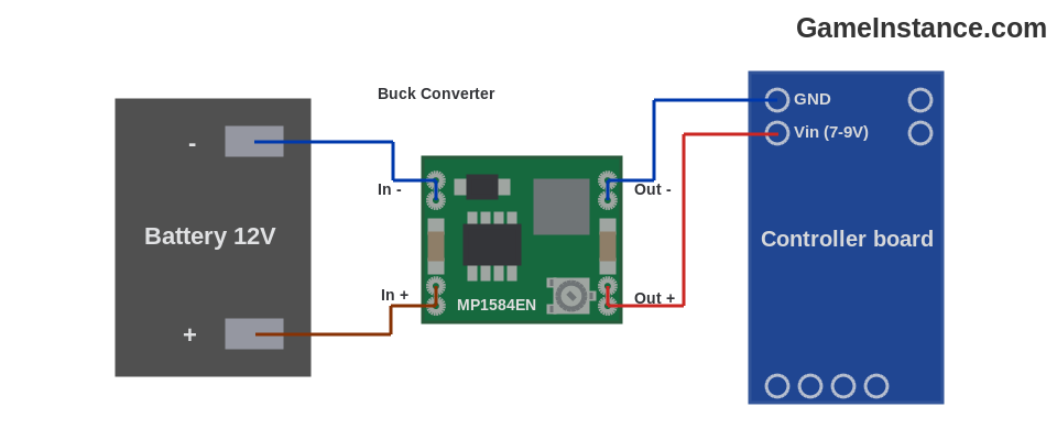 The irrigation system - power circuit featuring a buck converter for reducing the voltage down to 7-9 volts
The power supply
The circuit draws its power from a 12 V lead-acid battery through an adjustable buck converter capable of efficiently reduce the voltage to around 7 - 9 volts. Why that small voltage, you may ask. Well, there are three main reasons. The first has to do with the battery charging voltage, the second with the pumping speed and third, with efficiency.
First and foremost, the lead-acid battery sees more that 12 volts during the charging cycle - in fact the voltage often exceeds 14 volts. The electric motor of the pump is rated for 12 volts and the regulator on the Arduino board also takes up to 12 volts. The main reason therefore is keeping the input voltage under control. Anywhere above 7 volts - to give some headroom to the Arduino regulator - and below 12 volts not to fry the aforementioned devices will do.
Second, at 12 volts my pump will fill the first bottle too fast. The flow will be too big for the overflow hole and that will lead to water spillage. One solution would have been to increase the diameter of the overflow hole or to increase the height of the bottle cascade. There was the alternative to reduce the pump voltage and, obviously, I went for that. I found that anything between 7 and 9 volts does the job.
The third is more of a beneficial side-effect. The energy consumption of the controller board was also reduced by using a smaller voltage at the RAW pin of the Arduino. Any voltage regulator transforms the (Vin - Vout)*I product into heat that gets dissipated through the package and thus lost. The efficiency of the buck converter is undeniably superior, there are virtually no losses and that is a sought-after factor in off-grid systems.
The bill
is not too long. It will be the build and the tweaking that will eat-up your time but if you follow my advices you will slalom the issues and get a working irrigator in no time. Here's the parts list:
BOM:
uC1 - 1x Arduino Pro Mini board with Atmega328p
R1-3, R5 - 4x 10K Ohm, 0.25 W, resistors
R4 - 1x 1K Ohm, 0.25 W, resistor
Q1 - 1x IRF540 N-Channel MOSFET
RTC1 - 1x DS3231, I2C real-time clock
SW1-3 - 3x switches
Buck Converter - 1x MP1584EN, 3A, adjustable step down converter
Miscellaneous - cables, plugs, PCB boards
Not part of this list is the battery charging circuit that keeps the 12 volts battery topped-up at all times.
Few tips
Keep the electronics as simple modules (eg. the controller board, the switches and the power supply) and interconnect them with cables and plugs. In case you need to debug or upgrade some, you do not want to solder them in/out of place around your plants. Expose or keep easy access to the serial pins of your MCU for on-system debugging - you'll thank me later. Build a protective case for the controller and the buck converter to prevent dust and water from ruining the electronics. Avoid using standard switches in water or water vapor for too long. You'll find it better to use custom made ones with higher closing pressure.
Check-out the previous post for details and keep an eye for the next post that will break down the software component of the system.