This post is about integrating the 2.4" TFT LCD display, powered by the NT35702 controller, in STM32F103C8 applications. The MCU in this presentation is soldered on the famous Blue Pill breakout board and linking them together, just like in the ATmega328 integration, is the Arduino IDE. You need to follow three steps - connections, library setup and sketch upload - and you're done.
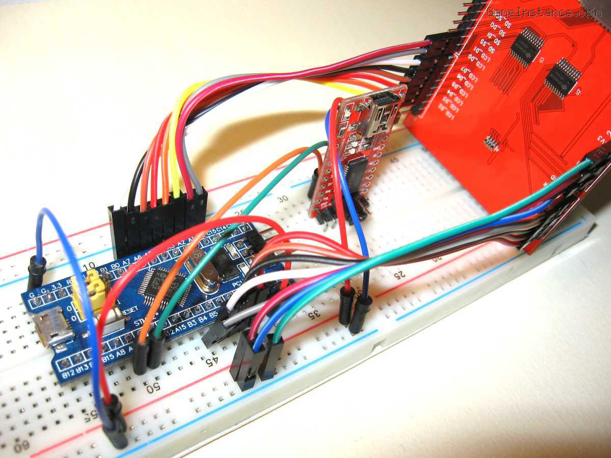 2.4" 320x240 NT35702 LCD and the STM32F103C8 Blue Pill board - breadboard setup
Connections
Subsets of the STM32's GPIO ports A and B are used for data port and control signaling. The exact pin connections are listed below.
2.4" TFT LCD Shield (35702) ---------------- STM32F103C8
----------------- control pins ------------------
LCD_RD --------------------------------------- PB4
LCD_WR --------------------------------------- PB5
LCD_RS ---------------------------------------- PB6
LCD_CS ---------------------------------------- PB7
LCD_RST --------------------------------------- PB8
------------------ data pins --------------------
LCD_D1 ---------------------------------------- PA1
LCD_D0 ---------------------------------------- PA0
LCD_D7 ---------------------------------------- PA7
LCD_D6 ---------------------------------------- PA6
LCD_D5 ---------------------------------------- PA5
LCD_D4 ---------------------------------------- PA4
LCD_D3 ---------------------------------------- PA3
LCD_D2 ---------------------------------------- PA2
------------------ power pins ------------------
5V -------------------------------------------- 5V
GND ------------------------------------------ GND
You have to use the 5V power for this configuration even though both the MCU and the display are 3.3V ready. That's because the 5V is required for illuminating the LCD. Both boards are capable of reducing from 5 to the 3.3 volts where and when needed.
Careful now!
Do not use 5V sources with 3.3V inputs. The power pins are marked accordingly but the inputs are not. Make sure you check the maximum rated voltages for the pins you're about to connect. That information is available in the datasheet.
Library setup
The Arduino code needs the Adafruit GFX for graphics and the STM32 specialization of the Adafruit TFT library. The first can be installed directly from the Arduino IDE: Sketch -> Include Library -> Manage Library menu. The second, however, has to be downloaded and installed manually from github. It's not that hard, just extract the zip file in the libraries folder of your Arduino path, then restart the IDE.
The code
is very similar with the one in the ATmega328 implementation. Here it is:
#include <Adafruit_ILI9341_8bit_STM.h>
#include <Adafruit_GFX.h>

#define	BLUE    0x001F
#define YELLOW  0xFFE0

Adafruit_ILI9341_8bit_STM tft;

void setup(void) {
  //
  Serial.begin(9600);
  tft.begin();
  gameInstance();
}

void loop(void) {
  //
  delay(1000);
}

void gameInstance() {
  //
  tft.setRotation(1);
//  tft.invertDisplay(true);
  tft.fillScreen(BLUE);
  tft.setCursor(15, 100);
  tft.setTextColor(YELLOW);
  tft.setTextSize(3);
  tft.println("GameInstance.com");
}
As you may observe, the forked TFT library offers no way of configuring the pins. That's because of the GPIO port configuration of the STM32 and the intricacies that come from it. Basically one has to specify the GPIO port name and the pin number between 0 and 15, which is not exactly the Arduino way of doing things. One needs to understand that this is a working and free solution and the developer's efforts need be appreciated regardless of the restrictions and the limitations deriving from it.
Closure
There is, however, a small issue with the integration. The colors are inverted - yellow is displayed as blue and blue as yellow - and either X or Y axis are reversed. The invertDisplay method call has no effect.
Update: The problem goes away if the call to setRotation is made in the setup method. Obviously, this is a workaround rather than a proper fix.
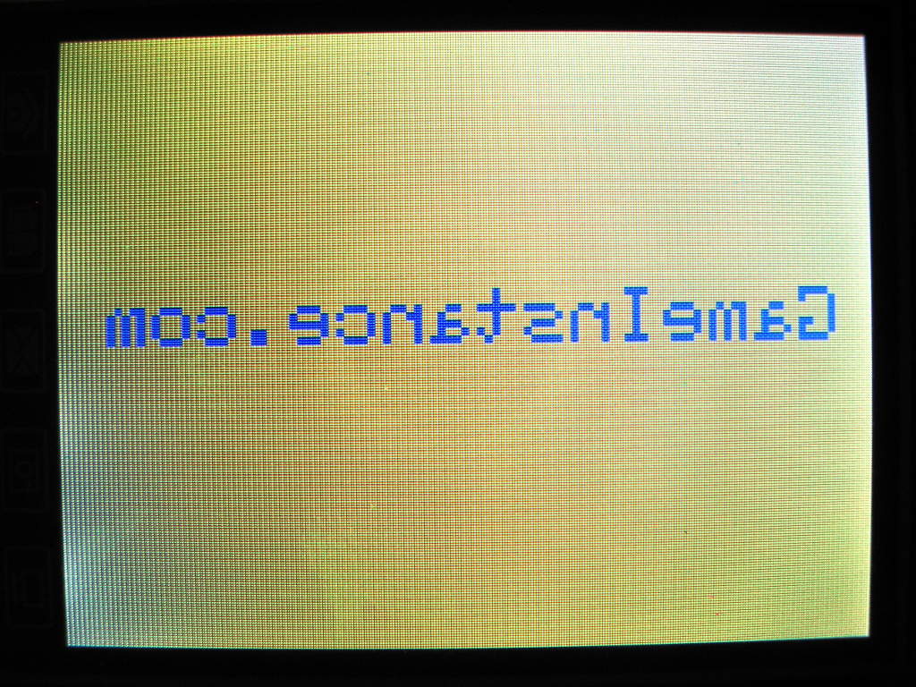 2.4" 320x240 NT35702 LCD - axis and color anomaly with the STM32 library
All these indicate a coding issue in one of the libraries, most likely in the STM32 fork, and hopefully it will be solved in the near future.
That aside, the configuration presented in this article is a cornerstone for more evolved embedded interfaced application. It will be the basis of the upgrade to the Digital Oscilloscope project.