For less than four dollars you get 320x240 pixels with 16 bit color depth on a 4:3 ratioed 2.4 inch diagonal display, resistive touchscreen and SD card reader. Quite a lot. The only down-side I see in it is the shield based construction. Breaking out more than 20 pins, on the other hand, wouldn't have been much prettier. The NT35702 controller, although ILI9341 compatible, gives novice DIY enthusiast headaches. If you found yourself having a hard time getting it to work, put that aspirin away, your pain is about to be alleviated. Just read along.
 2.4 inch TFT Display with ILI9341 compatible controller
The board construction is decent but one needs to be extra careful with the display itself. Unlike the Nokia 5110 LCD, this one has the screen glued with double-sided tape. The TFT is connected to the board with a flexible ribbon cable soldered in 37 points. In case you accidentally slide it away from the board, you'll have a really bad day. So keep that aspirin close-by. More annoying is the set of predefined icons on the side of the screen. The thing must have been a leftover part from a failed or discontinued mobile product, a PDA of some sort, that got reassigned instead of being scrapped. Long live the DIY community!
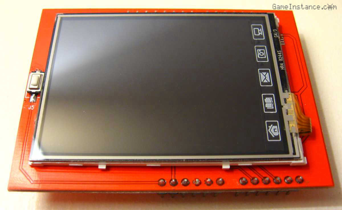 2.4 inch TFT Display Arduino shield - front side
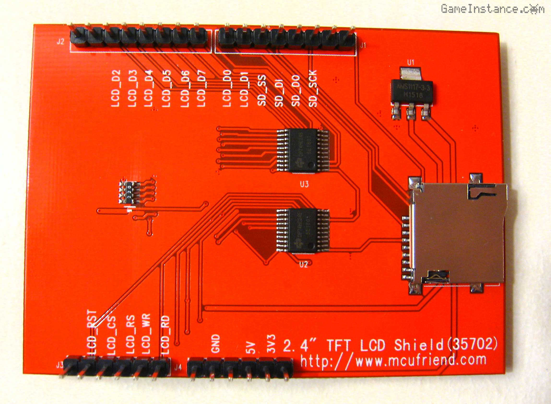 2.4 inch TFT Display Arduino shield - back side
The connections
Following the shield defaults, the connections are pretty straightforward. One needs just to follow those if using non-standard Arduino boards. I prefer the Pro and Pro Mini formats because they provide the bare essentials that fit well in any project. Besides, they're breadboard ready. The device uses analog output pins for control communication with the display controller, digital inputs as parallel data port and SPI port for the SD card reader. At this stage, there's no need to change this arrangement.
2.4" TFT LCD Shield (35702) ---------------- ATmega328
----------------- control pins ------------------
LCD_RD --------------------------------------- A0
LCD_WR --------------------------------------- A1
LCD_RS ---------------------------------------- A2
LCD_CS ---------------------------------------- A3
LCD_RST --------------------------------------- A4
------------------ data pins --------------------
LCD_D1 ---------------------------------------- 9
LCD_D0 ---------------------------------------- 8
LCD_D7 ---------------------------------------- 7
LCD_D6 ---------------------------------------- 6
LCD_D5 ---------------------------------------- 5
LCD_D4 ---------------------------------------- 4
LCD_D3 ---------------------------------------- 3
LCD_D2 ---------------------------------------- 2
--------------- SD card component ---------------
SD_SCK --------------------------------------- 13 (SPI SCK)
SD_DO ---------------------------------------- 12 (SPI MISO)
SD_DI ----------------------------------------- 11 (SPI MOSI)
SD_SS ----------------------------------------- 10 (SPI SS)
--------------- power connections ----------------
3V3 ------------------------------------------- NC
5V -------------------------------------------- 5V
GND ------------------------------------------ GND
The code
is borrowed from the Adafruit TFTLCD and GFX library examples. By the way, the aforementioned libraries need to be downloaded from the Arduino IDE. The only modification that needs to be made for the NT35702 controller is the addition of a line of code changing the detected chip identifier to ILI9341. These boards are detected as having id 0 and the Adafruit libraries don't know how to approach them. What you're doing is giving the library a hint about it. With that in mind, here's the code:
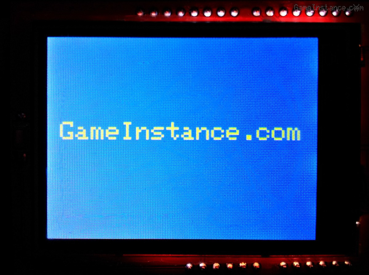
#include <Adafruit_GFX.h>    // Core graphics library
#include <Adafruit_TFTLCD.h> // Hardware-specific library

#define LCD_CS A3 // Chip Select goes to Analog 3
#define LCD_CD A2 // Command/Data goes to Analog 2
#define LCD_WR A1 // LCD Write goes to Analog 1
#define LCD_RD A0 // LCD Read goes to Analog 0
#define LCD_RESET A4 // Can alternately just connect to Arduino's reset pin

#define	BLACK   0x0000
#define	BLUE    0x001F
#define	RED     0xF800
#define	GREEN   0x07E0
#define CYAN    0x07FF
#define MAGENTA 0xF81F
#define YELLOW  0xFFE0
#define WHITE   0xFFFF

Adafruit_TFTLCD tft(LCD_CS, LCD_CD, LCD_WR, LCD_RD, LCD_RESET);

void setup(void) {
  //
  Serial.begin(9600);
  tft.reset();
  uint16_t identifier = tft.readID();
  Serial.print(F("TFT ID:"));
  Serial.println(identifier); // will display 0
  identifier = 0x9341;        // the workaround for the NT 35702 controller
  tft.begin(identifier);

  gameInstance();
}

void loop(void) {
  //
  delay(1000);
}

void gameInstance() {
  //
  tft.setRotation(1);
  tft.fillScreen(BLUE);
  tft.setCursor(15, 100);
  tft.setTextColor(YELLOW);
  tft.setTextSize(3);
  tft.println("GameInstance.com");
}
Once you've passed that phase, you're done integrating the display into your project. The Adafruit GFX lib offers enough graphic methods to go around, all being well documented and easy to understand. The examples they offer put them all into context, sometimes a better way to learn things.
Conclusions
Apart from the double-sided glue tape fixation and the cheesy icons, the display looks promising. It sports a lot of pixels on a decent sized surface and will suck thirteen pins from your MCU. It seems a good candidate for an upgrade to the ArduScope digital oscilloscope project. That, and many others, in the future posts.