I decided to replace my garage remote control. First and foremost because it is using conductive rubber pads instead of actual switches. They're not hard to press but to make the door open ... oh well, one needs the force be with'em. The remote never really works from the first button press and sometimes it doesn't even after the 20th. Yes, it is an old remote and one may say it has some character.
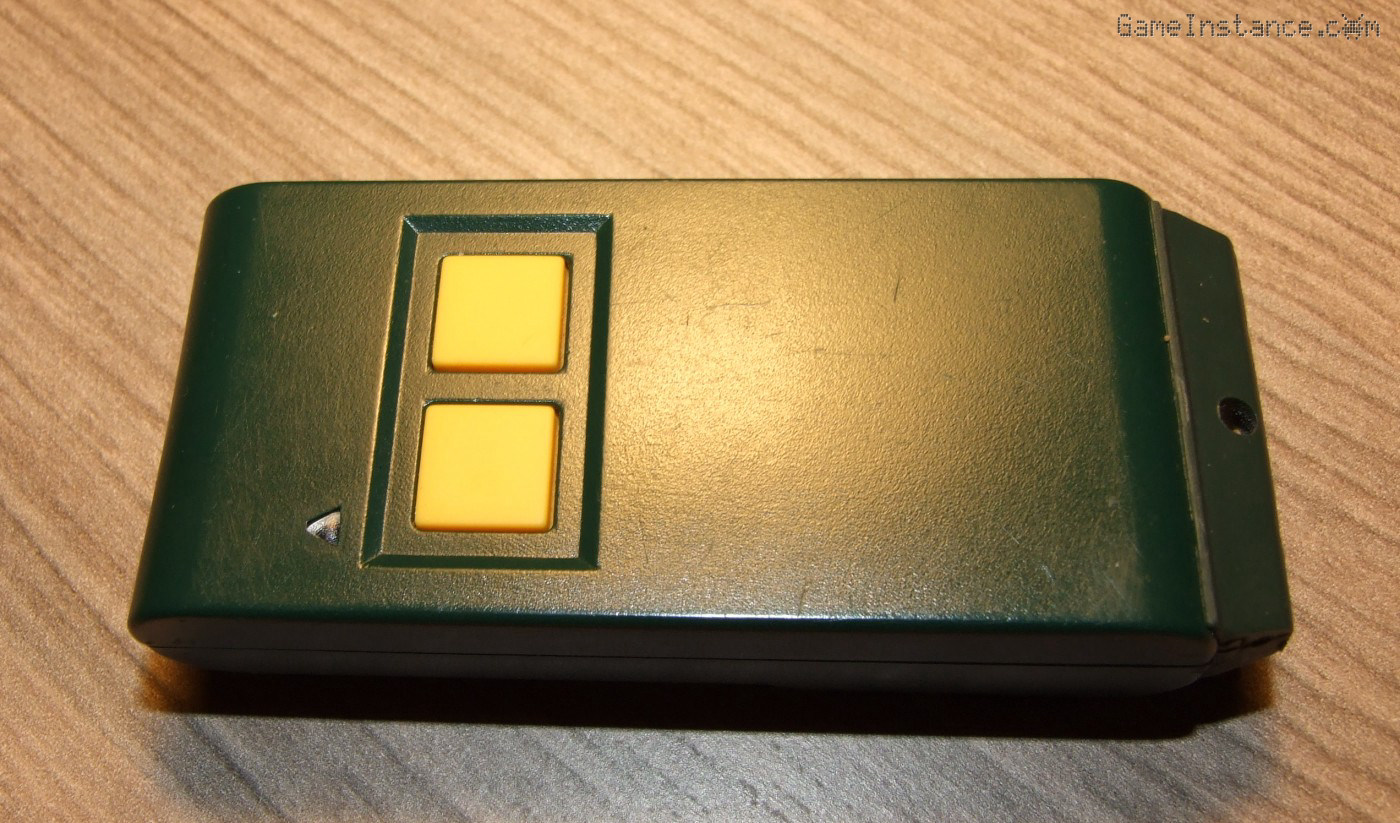 The old MPS/TF2E garage door remote control, featuring the obsolete conductive rubber pads.
So, I made the sensible choice and bought a new blank 433MHz remote. I tried to copy the code onto it and unsurprisingly, that failed. This article covers my attempt to decode the signal of the old remote control.
Before I continue
I should mention that cleaning the conductive pads doesn't improve their contact. It seems like if the button is not pressed hard enough, the signal isn't sufficiently powerful or accurate to open the door. I could place a micro-switch in between the rubber button and the board. Where would the fun be in that?
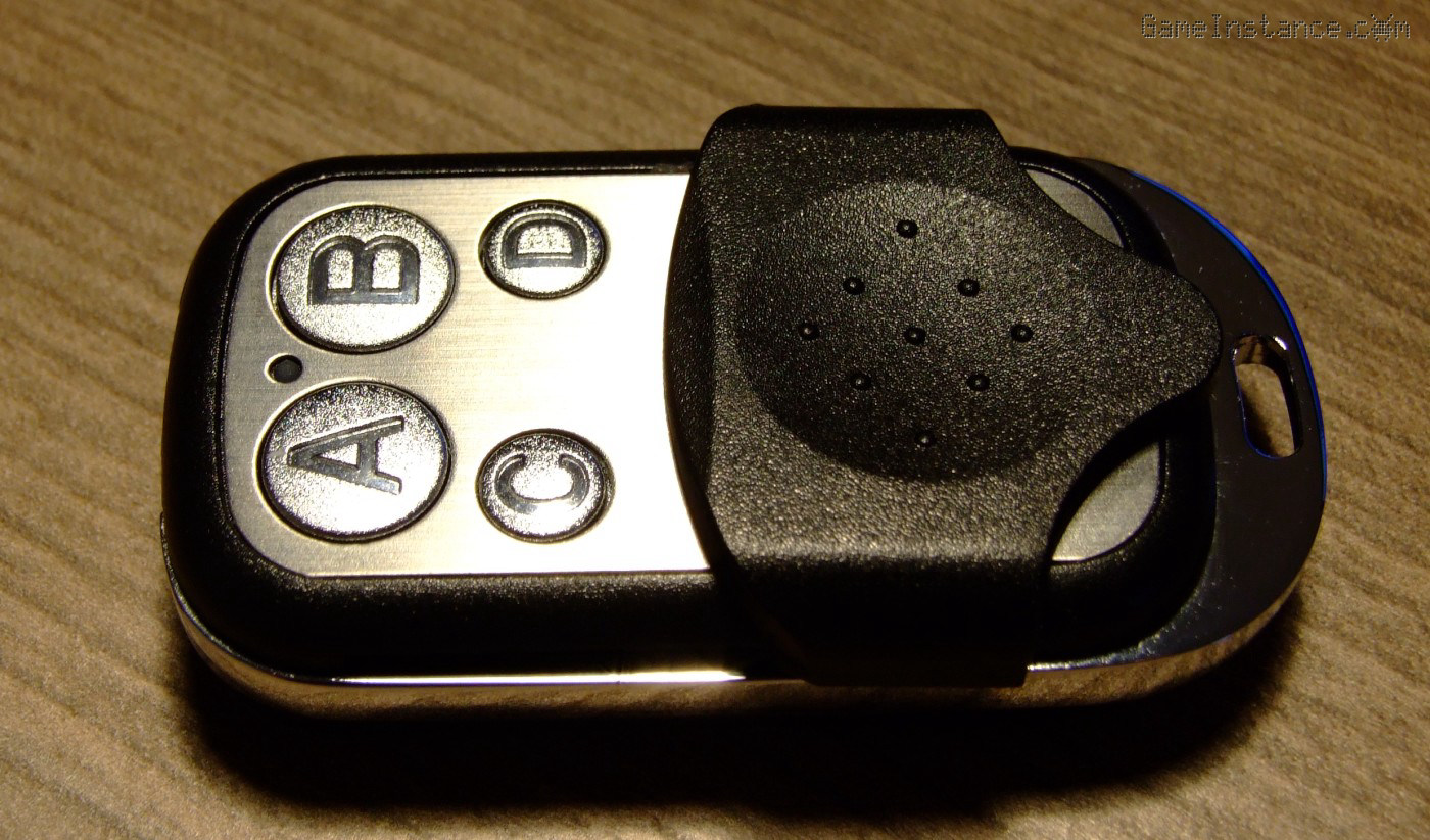 The new general purpose remote control - a compact and sturdy body with four proper buttons.
I bought the new remote control simply because it had a tough body and micro-switches for buttons. The fact that it has two more buttons did not appealed to me at the time but I figured they could be handy for later projects. It was a bargain and despite the fact that it was not mentioned as compatible with my old remote, I took it anyway. With the two remotes in close proximity I tried the copy procedure but that did not work.
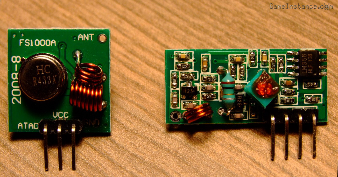 General purpose 433 MHz ASK transmitter (left) and receiver (right) kit.
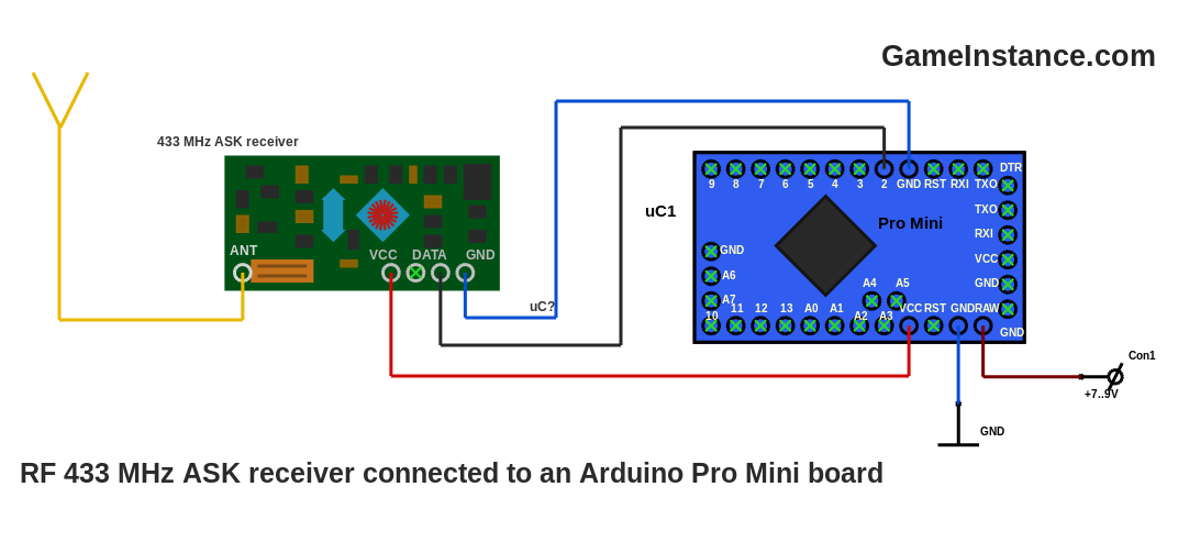
For the remainder of this experiment I have used general purpose 433 MHz emission and receiver circuits. Both use ASK modulation and as it turned out, so did the two remotes. I followed the instructions and connected the receiver to an Atmega 328p Arduino Pro Mini board. The antenna consists of a 17 cm wire, 1/4 of the wavelength for the 433 MHz carrier.
At first I used a very simple sketch that declared the DATA pin - Arduino pin 2 in this case - as an input and left it like that. In this circuit I hooked my STM32 O-scope and sniffed out the signal generated by the old remote. The remote emits a finite set of codes separated by sections of LOWs. I figured out that how 1 and 0 bits are coded, approximated their duty cycle values and measured the bit period, approximately 1 millisecond.
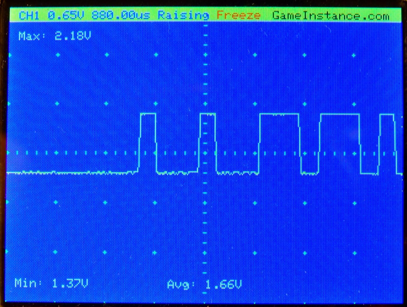 STM32 O-scope capture indicating the end of a sync section followed by the beginning of signal code: 00110...
While RC-Switch worked for the new remote control - giving a 24 bit code - it did not for the old one. However, with above info I was able to devise a sketch that would probe the signal at 128 K samples per second, enough to evaluate the codes and the duration of synchronization sections. The sketch is giving out the number of samples for each value - useful for decoding the bits - and during sync periods it prints-out the internal timestamp.
static const int PROBE = 2;

volatile int value, old = -1, cnt = 0;
extern volatile unsigned long timer0_millis;

inline void change(byte level, int cnt) {
  //
  Serial.print(level);
  Serial.print("::");
  Serial.println(cnt);
}

void setup () {
  //
  Serial.begin(250000);
  for (int i = 0; i < 32; i ++) pinMode(i, OUTPUT);
  pinMode(A0, OUTPUT);
  pinMode(A1, OUTPUT);
  pinMode(A2, OUTPUT);
  pinMode(A3, OUTPUT);
  pinMode(A4, OUTPUT);
  pinMode(A5, OUTPUT);
  pinMode(A6, OUTPUT);
  pinMode(PROBE, INPUT);
}

void loop() {
  //
  value = digitalRead(PROBE);
  if (old == value) {
    //
    cnt ++;
    if (cnt == 200) {
      //
      Serial.println(timer0_millis);
    }
  } else {
    //
    change(old, cnt);
    cnt = 1;
  }
  old = value;
}
I then wrote a html/js app that did the decoding and display of signal. Apparently, the remote sends a set of 15 code words and the app deciphered each and every one of them.
 A train of 15 code words issued by the remote and intercepted by the Atmega 328p circuit
Dear neighbors,
this message concerns you! For our safety and the security of our belongings the codes depicted in rest of this article have been altered. This tutorial is supposed to help others decode their remote controls and not to expose ourselves to unnecessary risks.
The word codes have 37 bits, one of them is represented below, and are separated by 40 ms of sections. For the purpose of this presentation, the breaks between the code words were reduced to improve the signal readability.
 One of the code words: 0011010101010110011110010111111111111 prefixed with a 40 ms sync line
Among the conclusions: this very popular new generic remote is not compatible with the MPS/TF2E. Therefore the later cannot be duplicated using the on-the-fly code copy. However, I am planning on fully reproducing the remote using an Arduino and the 433 MHz transmitter counterpart. If that succeeds I will be attempting a mod/hack on the generic remote to make it support this exotic system. That, and many others, in a future post. Keep an eye out for updates!
Update: Check-out part 2, Replicating 433 MHz Remote Control Signals.