I've ended my previous post with the declared intention of creating a UV exposure box using LEDs powered directly from the grid, relying on the same principle as some consumer LED lamps. This article focuses on identify the key components of the circuit driving the LEDs and on finding the best solution to satisfy design requirements relying on measurements of UV LED illumination vs. voltage.
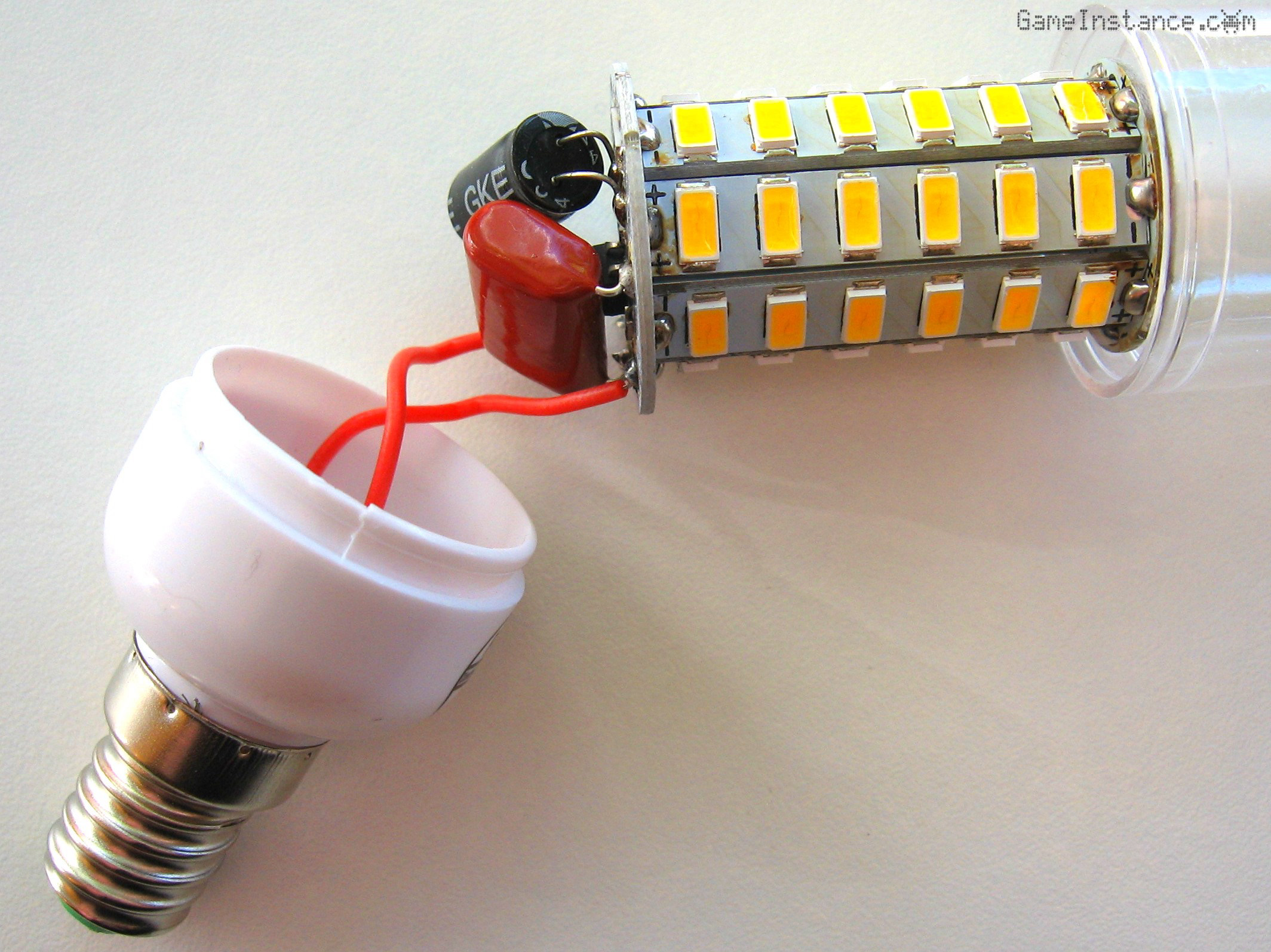
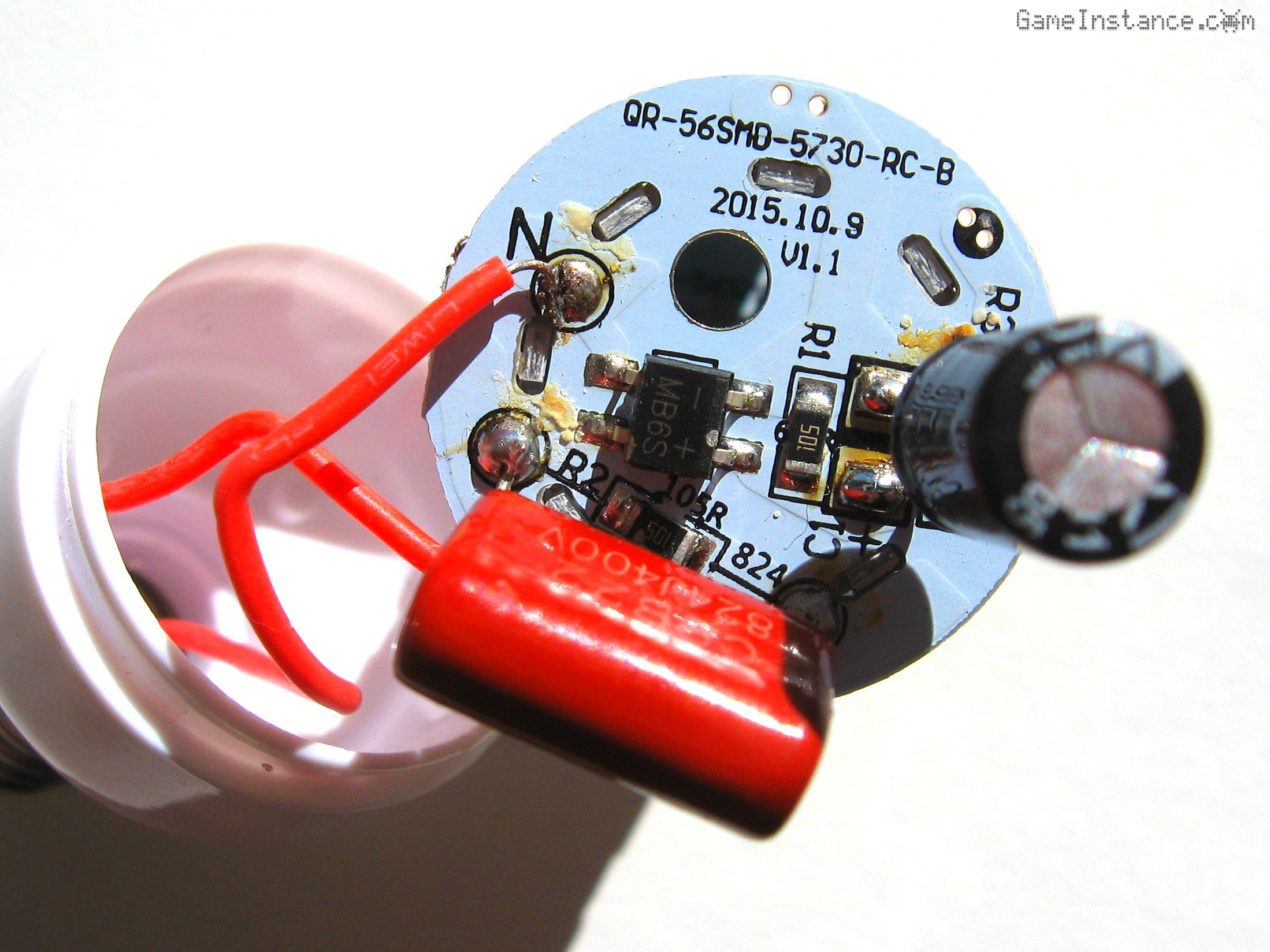
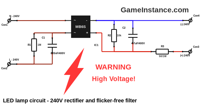
Here's how a corn cob shaped LED lamp looks like on the inside. Behind the LED cob there's a round PCB that contains the electronic components needed to drive the LEDs. The most important part is the MB6S, a full-wave bridge rectifier. The rectifier is fed through a coupling capacitor that blocks DC currents from entering the lamp. The rectified voltage is smoothened by a decoupling capacitor. Its effect is the minimization of illumination flicker. Both capacitors have a 1 MOhm resistor connected in parallel to discharge them in a reasonable amount of time, reducing the risk of an electric shock while handling the lamp.
The cob is composed of smaller boards containing series of LEDs. For extra rigidity and better heat dissipation, it is soldered backs to the electronics PCB. To further help with the heat dissipation, the bulb has a set of holes on to top of the case.
However, this design is not flawless. I had two such LED lamps and they all broke in less than a year of normal use. That's way under their rated life span. Both gave in immediately after they were turned on with an electric arcing sound coming from the light switch. My assumption is that the coupling capacitor in combination with the light switch imperfections became a voltage doubling circuit that exposed the LEDs to voltage spikes beyond the max values. Consequently, the weakest LED in the series would break and this is exactly what happened to both.
This won't happen in my circuit because the relay will turn on the circuit almost instantly compared with any hand actioned light switch. Consequently there will be little to no transients while turning on the circuit. Still, the relay is a electro-mechanical component that would wear-down eventually. However, the box won't be used on a daily basis so I expect it to function for a number of years. Reiterating, the main reason I chose the relay was because it offers galvanic insulation between the Arduino's 5V circuit and the high voltage LED light component.
Warning:
This project involves HIGH VOLTAGE! Touching a high voltage live wire is DEADLY! Please take proper precautions if you are attempting to reproduce it.
How many LEDs
can be connected in series? To answer that, one needs to know the voltage drop on a LED producing the best light intensity without surpassing its maximum rated current. Also, remember that the 240 V AC is expressed in RMS. That means the rectified and filtered DC voltage, representing the average value, will be around 216 V. This will be applied to the series of LEDs through a current limiting resistor that will absorb the grid voltage variations.
LED voltage drop
varies logarithmically with the current or otherwise put, the current through the LED grows exponentially with the applied voltage. What this means is that beyond a certain point, the slightest voltage offset yields huge current variations - sometimes well over the maximum current the LED can stand. The maximum rated voltage is that certain point. Few millivolts above that value and the current will skyrocket. This exponential voltage-current relation makes LEDs a bit trickier to power than other consumers. In fact it is best to power them at constant current, giving them a bit less than the maximum rating. However, that is unfeasible in this case and so the current limiting resistor is the best option.
Measurements have shown
that the illumination, as it was measured by the test rig, seems to vary linearly with the voltage. Consequently, the illumination produced by an LED at half of its maximum current is in fact more than half of the illumination generated at the maximum current. With that in mind and having chosen to build the box with a total of 200 LEDs, I'm left with one option: splitting the 200 in three parallel circuits of around 66-67 series LEDs. This yields a voltage drop of 3.23-3.27 V per LED, giving an approximate illumination of 0.23 Ohm-3 which is close to the 0.28 Ohm-3 produced by the LED at maximum current.
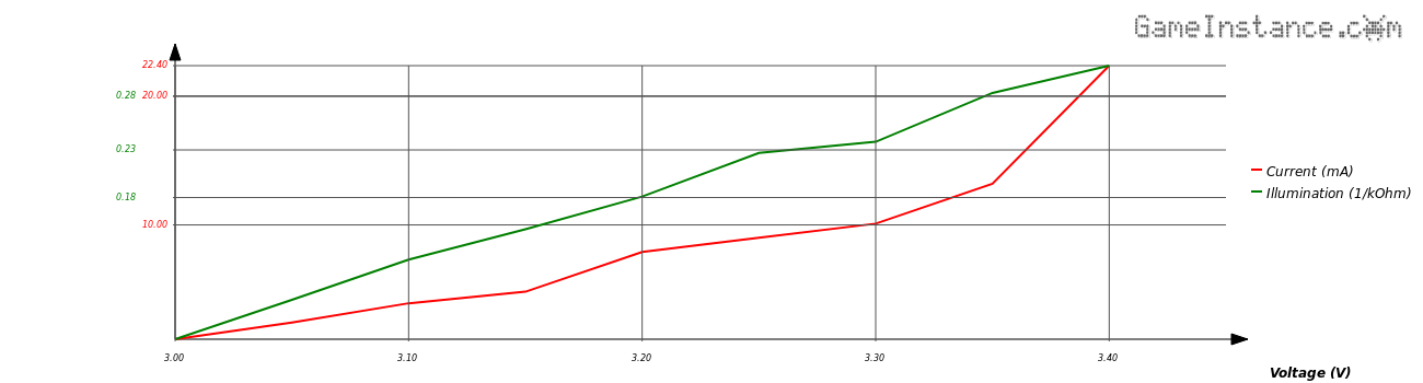
The test rig was composed of a UV LED connected optically with a random photoresistor. The voltage was incremented with a step of 50 mV from 3 V up to 3.4 V so that the LED current and illumination can be measured. Remember that the photoresistor's resistance is inversely proportional with the applied illumination. Given the fact that I'm using a component with unknown specifications, hence the aforementioned randomness, there's no rigorous relation between illumination and resistance. As such, the illumination has been expressed directly using the measured value, in Ohm-1.
Warning:
UV radiation is harmful for your eyes. Do not look directly into the light produced by the UV LEDs. Use protective sunglasses and even so avoid long exposure.
The current limiting resistor
will keep a steady current as the grid voltage fluctuates. So what resistance needs it have? Well, a low value will translate in higher current variations and that isn't necessarily what we're after. A high value will keep the current almost constant but the power dissipation on that resistor will be higher and the voltage drop per LED will be smaller. A good compromise has been chosen experimentally and that is 330 Ohm. In a series of 66 LED, the resistor will further reduce the current to 8.3 mA, giving a 0.19 Ohm-3 illumination. This is still more than half the illumination the LED can produce.
Concluding
The UV box will have three parallel circuits of 66-67 LEDs in series on two exposure boards - top and bottom - powered from the rectified grid voltage (240V AC in this case). All components from the defective LED lamp will be transplanted onto a small rectangular prototyping board that will fit better into the box.
Update: Check-out Part 3 - Building the box.