If you have ever built automations that employed switches for limit detection most likely you had problems with mechanical wear or contaminated contacts that, over the time, led to failures. You must have found the Hall effect sensor to be a viable alternative with almost no drawbacks. If you never heard of or used such a sensor, keep on reading. This won't take long.
Hall Effect means generating a small, yet detectable, voltage in the presence of a magnetic field. Circuits such as A3144 amplify the voltage without a negative feed-back - sort of infinitely - and then give that out. It sports a hysteresis loop to avoid oscillations and an open collector output to satisfy a rich palette of user circuits. Compared with the classic switch it still is expensive but when reliability is your top priority, and it always is, it worths every penny.
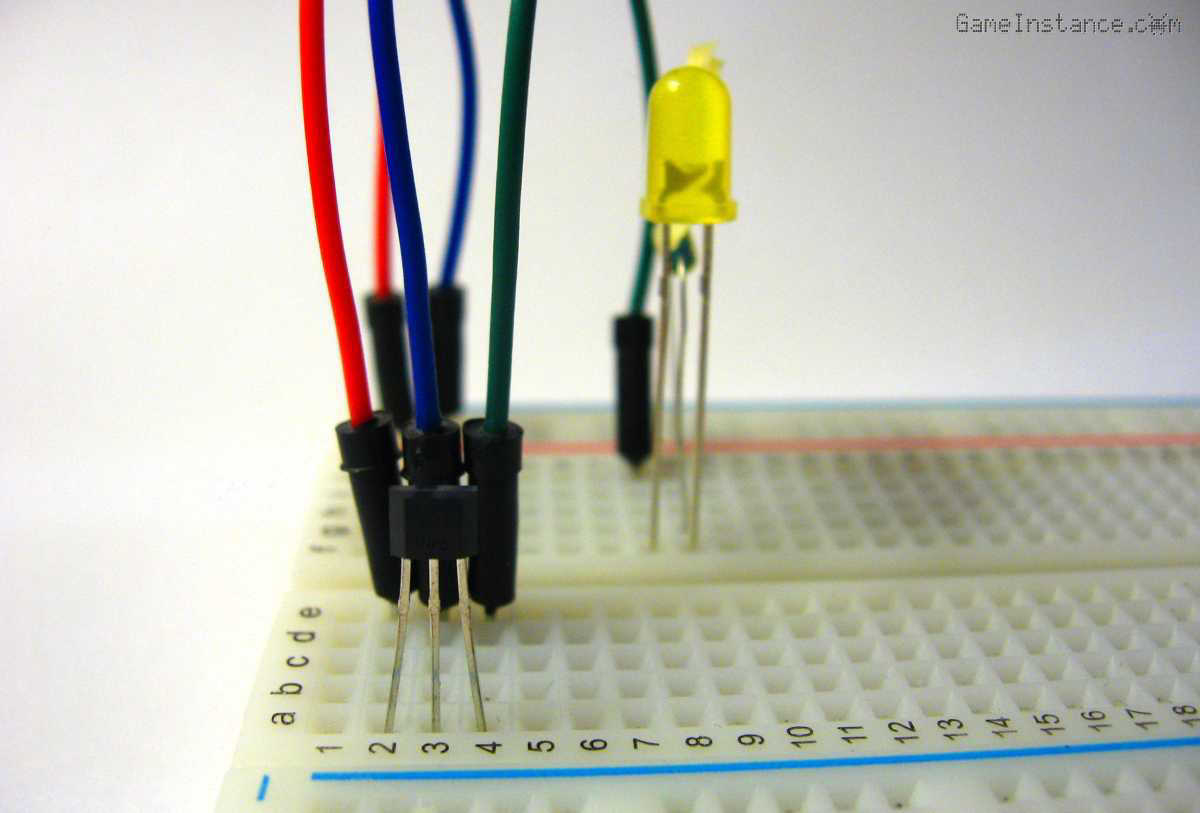 Hall Effect Sensor A3144 Switching LED - Breadboard Setup
So, open collector means that the output is either high or low impedance. At idle the output is high impedance and when a magnet is brought in its vicinity, the A3144 turns low impedance. To understand these states, the user circuit needs a pull-up resistor. That resistor will keep A3144's output voltage around the user circuit's Vcc at idle and around the GND voltage when activated.
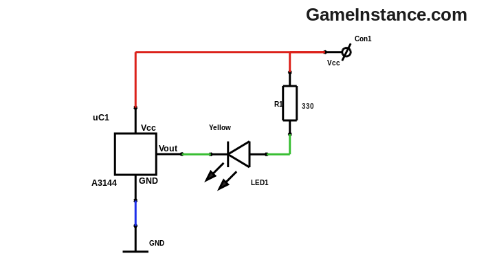 Hall Effect Sensor A3144 Switching LED - schematic
Bill Of Materials:
uC1 - A3144 Hall effect switch
LED1 - Yellow LED
R1 - 330 Ohm
Breadboard
Jumper Wires
In the schematic above, the user circuit is made of a LED that's lit by bringing a magnet next to the sensor. Pulling up the A3144's output is a 330 ohm resistor limiting the LED current to less than 10mA when active. The simplest test possible!
Warning:
The A3144's open collector internal transistor supports a current of up to 25mA. Anything above that value will fry the sensor thus rendering it useless. For higher current output you must use an external switching transistor.
Observe that in this case both the Hall effect sensor and the user circuit use the same Vcc. However, while the supply voltage for the sensor can be as low as 4.5 volts, the user circuit may expose its output to up to 28 volts. Again, this is a simple setup that proves helpful for testing and calibrating your automation rig.
The Hall effect sensors found their success in items we take for granted like cars, bikes or gadgets. It is used to accurately determine position in joysticks and accelerator pedals. For many years, the simplified switching version of Hall effect sensors (such as the A3144) proved their efficiency timing brushless electric motors, drive shafts or detecting wheel lock in anti-lock braking systems. As electric current generates a magnetic fields - remember the rule of right hand thumb and fingers - the same effect forms the basis of shuntless current measurement. This won't include all uses, that wasn't the purpose.
Do remember that Hall effect sensors can replace mechanical switches and potentiometers whenever robustness and reliability are paramount.